Chapter 6: Circuits

Chapter 6: Circuits
Science Mastery Assessment
Every pre-med knows this feeling: there is so much content I have to know for the MCAT! How do I know what to do first or what’s important?
While the high-yield badges throughout this book will help you identify the most important topics, this Science Mastery Assessment is another tool in your MCAT prep arsenal. This quiz (which can also be taken in your online resources) and the guidance below will help ensure that you are spending the appropriate amount of time on this chapter based on your personal strengths and weaknesses. Don’t worry though— skipping something now does not mean you’ll never study it. Later on in your prep, as you complete full-length tests, you’ll uncover specific pieces of content that you need to review and can come back to these chapters as appropriate.
How to Use This Assessment
If you answer 0–7 questions correctly:
Spend about 1 hour to read this chapter in full and take limited notes throughout. Follow up by reviewing all quiz questions to ensure that you now understand how to solve each one.
If you answer 8–11 questions correctly:
Spend 20–40 minutes reviewing the quiz questions. Beginning with the questions you missed, read and take notes on the corresponding subchapters. For questions you answered correctly, ensure your thinking matches that of the explanation and you understand why each choice was correct or incorrect.
If you answer 12–15 questions correctly:
Spend less than 20 minutes reviewing all questions from the quiz. If you missed any, then include a quick read-through of the corresponding subchapters, or even just the relevant content within a subchapter, as part of your question review. For questions you got correct, ensure your thinking matches that of the explanation and review the Concept Summary at the end of the chapter.
- If a defibrillator passes 15 A of current through a patient’s body for 0.1 seconds, how much charge goes through the patient’s skin?
- 0.15 C
- 1.5 C
- 15 C
- 150 C
- A student places an ammeter with negligible resistance in parallel with a resistor to determine the amount of current that passes through the resistor. Does the student obtain an accurate reading?
- Yes, because the student used an ammeter with negligible resistance.
- Yes, because the current going through parallel paths is equal.
- No, because the ammeter should have infinite resistance.
- No, because an ammeter in parallel changes the current through the resistor.
- The resistance of two conductors of equal cross-sectional area and equal lengths are compared, and are found to be in the ratio 1:2. The resistivities of the materials from which they are constructed must therefore be in what ratio?
- 1:1
- 1:2
- 2:1
- 4:1
- A voltaic cell provides a current of 0.5 A when in a circuit with a 3 Ω resistor. If the internal resistance of the cell is 0.1 Ω, what is the voltage across the terminals of the battery when there is no current flowing?
- 0.05 V
- 1.5 V
- 1.505 V
- 1.55 V
- A transformer is a device that takes an input voltage and produces an output voltage that can be either larger or smaller than the input voltage, depending on the transformer design. Although the voltage is changed by the transformer, energy is not, so the input power equals the output power. A particular transformer produces an output voltage that is 300 percent of the input voltage. What is the ratio of the output current to the input current?
- 1:3
- 3:1
- 1:300
- 300:1
- Given that R1 = 20 Ω, R2 = 4 Ω, R3 = R4 = 32 Ω, R5 = 15 Ω, and R6 = 5 Ω, what is the total resistance in the setup shown below?
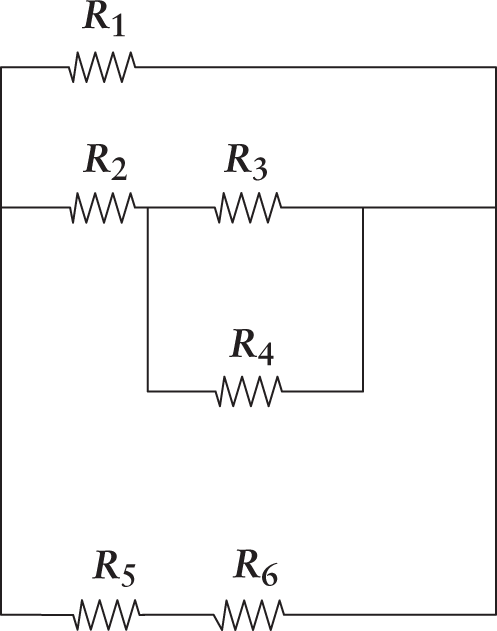
- 0.15 Ω
- 6.67 Ω
- 16.7 Ω
- 60 Ω
- How many moles of electrons pass through a circuit containing a 100 V battery and a 2 Ω resistor over a period of 10 seconds? (Note: F=9.65×10⁴Cmol e−.)
- 5.18 × 10⁻³ moles
- 500 moles
- 5.18 × 10³ moles
- 5.2 × 10⁶ moles
- In the circuit below, what is the voltage drop across the 23 Ω resistor?
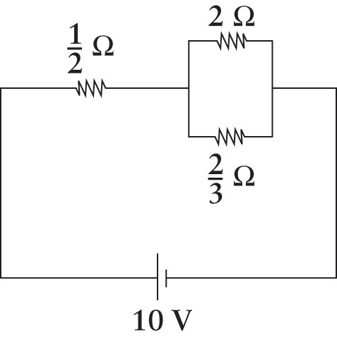
- 12 V
- 23 V
- 5 V
- 7.5 V
- If the area of a capacitor’s plates is doubled while the distance between them is halved, how will the final capacitance (Cf) compare to the original capacitance (Ci)?
- Cf = Ci
- Cf=12Ci
- Cf = 2Ci
- Cf = 4Ci
- The energy stored in a fully charged capacitor is given by U=12 CV2. In a typical cardiac defibrillator, a capacitor charged to 7500 V has a stored energy of 400 J. Based on this information, what is the charge on the capacitor in the cardiac defibrillator?
- 1.1 × 10⁻⁵ C
- 5 × 10⁻² C
- 1.1 × 10⁻¹ C
- 3.1 × 10⁶ C
- A 10 Ω resistor carries a current that varies as a function of time as shown. How much energy has been dissipated by the resistor after 5 s?
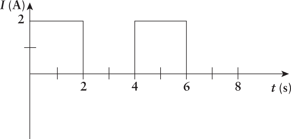
- 40 J
- 50 J
- 120 J
- 160 J
- In the figure below, six currents meet at point P. What is the magnitude and direction of the current between points P and x?
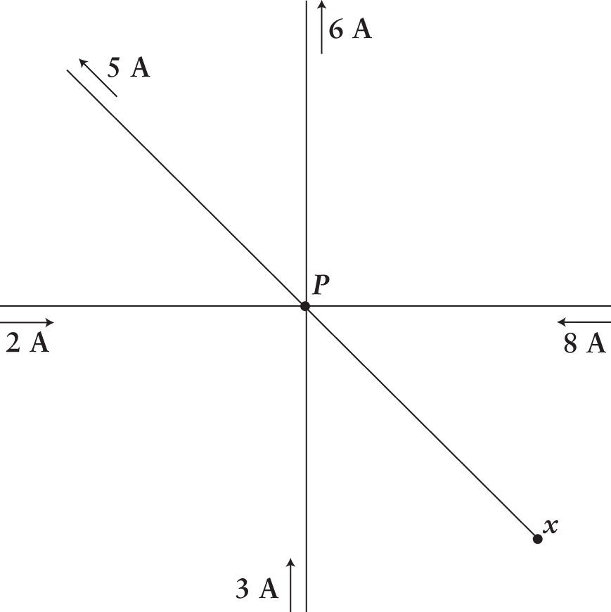
- 2 A, toward x
- 2 A, toward P
- 10 A, toward x
- 10 A, toward P
- Which of the following will most likely increase the electric field between the plates of a parallel plate capacitor?
- Adding a resistor that is connected to the capacitor in series
- Adding a resistor that is connected to the capacitor in parallel
- Increasing the distance between the plates
- Adding an extra battery to the system
- Each of the resistors shown carries an individual resistance of 4 Ω. Assuming negligible resistance in the wire, what is the overall resistance of the circuit?
- 16 Ω
- 8 Ω
- 4 Ω
- 3 Ω
- Which of the following best characterizes ideal voltmeters and ammeters?
- Ideal voltmeters and ammeters have infinite resistance.
- Ideal voltmeters and ammeters have no resistance.
- Ideal voltmeters have infinite resistance, and ideal ammeters have no resistance.
- Ideal voltmeters have no resistance, and ideal ammeters have infinite resistance.
Answer Key
- B
- D
- B
- D
- A
- B
- A
- C
- D
- C
- C
- A
- D
- D
- C
Chapter 6: Circuits
CHAPTER 6
CIRCUITS
In This Chapter
6.1 Current
Conductivity
Current
Circuit Laws
6.2 Resistance
Properties of Resistors
Ohm’s Law and Power
Resistors in Series and Parallel
6.3 Capacitance and Capacitors
Properties of Capacitors
Dielectric Materials
Capacitors in Series and Parallel
6.4 Meters
Ammeters
Voltmeters
Ohmmeters
Concept Summary
CHAPTER PROFILE
The content in this chapter should be relevant to about 16% of all questions about physics on the MCAT.
This chapter covers material from the following AAMC content category:
4C: Electrochemistry and electrical circuits and their elements
Introduction
Batteries, electric circuits, and electrical equipment pervade our everyday world. Think of any piece of equipment, tool, or toy that has a battery or a power cord, and you’ve identified an object that depends on the movement of electrons and the delivery of electric potential energy to carry out its function. Turn on a light, watch TV, or toast bread, and you can literally watch electrons at work as they emit light. Electricity is not restricted to the inorganic, material world—even in our bodies, we find electricity serving a key role in a number of physiological functions. Not only do the neurons in our brain and conduction system in our heart rely on electricity, but so does every cell that utilizes mitochondria to carry out oxidative phosphorylation.
This chapter reviews the essentials of circuits. From this broad knowledge base, we will draw on specific topics within circuit theory: conductivity, electromotive force (emf), resistance, power, Kirchhoff’s laws, resistors, capacitors, meters, and series and parallel arrangements of circuit components. As you encounter the concepts of this chapter and the equations associated with them, remember this: the MCAT approaches the topic of circuits with a greater emphasis on the concepts than on the math. You will be expected to calculate, say, the equivalent resistance for resistors in series or parallel, but the circuits you encounter on Test Day will, on the whole, be simpler than what you may have seen in your college physics class.
6.1 Current
LEARNING OBJECTIVES
After Chapter 6.1, you will be able to:
- Recall the definitions of current, voltage, electromotive force (emf), and conductivity, and the SI units for each
- Compare the conductivity of two solutions, given their component ions
- Describe the relationship between voltage sources and voltage drop
- Use Kirchhoff’s laws to describe the flow of electrons through a circuit
In the last chapter we examined the behaviors of still charges, but in most cases we are interested in the movement of charge, or current. Because of historical conventions, current is considered the flow of positive charge—even though only negative charges are actually moving. Any conductive substance may act as a medium through which current can pass.
Conductivity
Conductivity can be divided into two categories: metallic conductivity, as seen in solid metals and the molten forms of some salts, or electrolytic conductivity, as seen in solutions. Conductance is the reciprocal of resistance, a property we will examine in detail later. The SI unit for conductance is the siemens (S), sometimes given as siemens per meter (Sm) for conductivity.
Metallic Conductivity
Some materials allow free flow of electric charge within them; these materials are called electrical conductors. Metal atoms can easily lose one or more of their outer electrons, which are then free to move around in the larger collection of metal atoms. This makes most metals good electrical and thermal conductors. The metallic bond has often been visualized as a sea of electrons flowing over and past a rigid lattice of metal cations. While this model is generally appropriate for the MCAT, metallic bonding is more accurately described as an equal distribution of the charge density of free electrons across all of the neutral atoms within the metallic mass.
BRIDGE
Remember that the metals are found on the left side of the periodic table. These are the atoms with the lowest ionization energies; thus, it is easiest for these atoms to lose electrons. Due to this weak hold, electrons are free to move around in the metal, conducting electrical charges. Periodic trends are discussed in Chapter 2 of MCAT General Chemistry Review.
Electrolytic Conductivity
While not substantially different from metallic conductivity, it is important to note that electrolytic conductivity depends on the strength of a solution. Distilled deionized water has such a low ion concentration that it may be considered an insulator, while sea water and orange juice are excellent conductors. Conductivity in an electrolyte solution is measured by placing the solution as a resistor in a circuit and measuring changes in voltage across the solution. Because concentration and conductivity are directly related, this method is often used to determine ionic concentrations in solutions, such as blood. One caveat is that conductivity in nonionic solutions is always lower than in ionic solutions. While the concentration of total dissolved solids does relate to conductivity, the contribution of nonionic solids is much, much less important than ion concentration.
Current
Chapter 5 of MCAT Physics and Math Review introduced the concept of electrical current: the flow of charge between two points at different electrical potentials connected by a conductor, such as a copper wire. The magnitude of the current I is the amount of charge Q passing through the conductor per unit time ∆t, and it can be calculated as:
I=QΔt
Equation 6.1
The SI unit of current is the ampère (1 A=1 Cs). Charge is transmitted by a flow of electrons in a conductor, and because electrons are negatively charged, they move from a point of lower electrical potential to a point of higher electrical potential (and, in doing so, reduce their electrical potential energy). By convention, however, the direction of current is the direction in which positive charge would flow (from higher potential to lower potential). Thus, the direction of current is opposite to the direction of actual electron flow. The two patterns of current flow are direct current (DC), in which the charge flows in one direction only, and alternating current (AC), in which the flow changes direction periodically. Direct current is produced by household batteries, while the current supplied over long distances to homes and other buildings is alternating current. Our discussion of circuits will assume direct current, which is tested on the MCAT to the exclusion of alternating current.
A potential difference (voltage) can be produced by an electrical generator, a galvanic (voltaic) cell, a group of cells wired into a battery, or—as seen in classic science fair projects—even a potato. When no charge is moving between the two terminals of a cell that are at different potential values, the voltage is called the electromotive force (emf or ε). Do not be misled by this term, as emf is not actually a force; it is a potential difference (voltage) and, as such, has units of joules per coulomb (1 V=1 JC) —not newtons. It may be helpful to think of emf as a “pressure to move” that results in current, in much the same way that a pressure difference between two points in a fluid-filled tube causes the fluid to flow.
BRIDGE
The standard batteries in flashlights and remote controls are examples of galvanic (voltaic) cells. These house spontaneous oxidation–reduction reactions that generate emf as a result of differences in the reduction potentials of two electrodes. Electrochemistry is discussed in Chapter 12 of MCAT General Chemistry Review.
Circuit Laws
Currents (and circuits in general) are governed by the laws of conservation. Charge and energy must be fully accounted for at all times and can be neither created nor destroyed. An electric circuit is a conducting path that usually has one or more voltage sources (such as a battery) connected to one or more passive circuit elements (such as resistors). Kirchhoff’s laws are two rules that deal with the conservation of charge and energy within a circuit.
Kirchhoff’s Junction Rule
At any point or junction in a circuit, the sum of currents directed into that point equals the sum of currents directed away from that point. This is an expression of conservation of electrical charge and can be expressed as
Iinto junction = Ileaving junction
Equation 6.2
KEY CONCEPT
Kirchhoff’s junction rule is just like a fork in a river. There are a certain number of water molecules in a river, and at any junction, that number has to go in one of the diverging directions; no water molecules spontaneously appear or disappear. The same holds true for the amount of current at any junction.
Example: Three wires (a, b, and c) meet at a junction point P, as shown below. A current of 5 A flows into P along wire a, and a current of 3 A flows away from P along wire b. What is the magnitude and direction of the current along wire c?
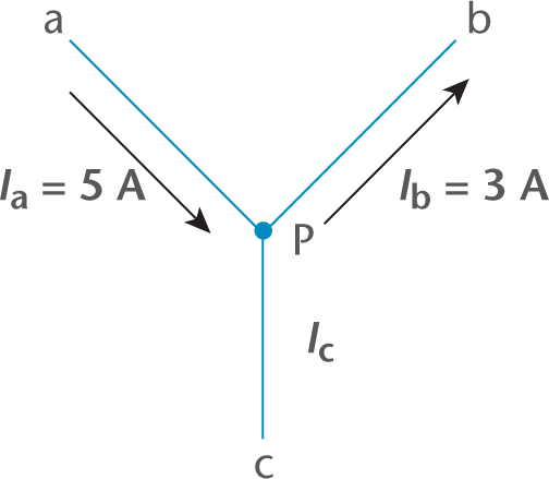
Solution: The sum of currents entering P must equal the sum of the currents leaving P. Assume for now that Ic flows out of P. If we find that it is negative, then we know the current must be going the other direction (into P).
Ia=Ib+Ic5 A=3 A+IcIc=2 A
Thus, a current of 2 A flows out of P along wire c.
Kirchhoff’s Loop Rule
Around any closed-circuit loop, the sum of voltage sources will always be equal to the sum of voltage (potential) drops. This is a consequence of the conservation of energy. All the electrical energy supplied by a source gets fully used up by the other elements within that loop. No excess energy appears, and no energy disappears that cannot be accounted for. Of course, energy can be changed from one form to another, so the kinetic energy of the electrons can be converted to thermal energy, light, or sound by the particular apparatus that is connected to the circuit. Remember that although Kirchhoff’s loop rule is a consequence of the law of conservation of energy, this law is in terms of voltage (joules per coulomb), not just energy (joules). This can be expressed mathematically as
Vsource = Vdrop
Equation 6.3
KEY CONCEPT
If all of the voltage wasn’t “used up” in each loop of the circuit, then the voltage would build after each trip around the circuit, which is impossible.
MCAT CONCEPT CHECK 6.1
Before you move on, assess your understanding of the material with these questions.
- Define the following terms and provide their SI units.
- Current:
_________________________________
- Voltage:
_________________________________
- Electromotive force (emf):
_________________________________
- Conductivity:
_________________________________
- Which likely has a higher conductivity: 1 M glucose or 0.25 M NaCl? Why?
_________________________________
- True or False: In a circuit, the number of electrons entering a point and leaving that point are the same.
- True or False: The sum of the voltage sources in a circuit is equal to the sum of the voltage drops in that circuit.
6.2 Resistance
LEARNING OBJECTIVES
After Chapter 6.2, you will be able to:
- Recall how the physical properties of a resistor determine its resistance
- Apply the formulas that connect power to current, voltage, and resistance
- Describe how internal resistance of a battery impacts the circuit system
- Contrast the effects of a resistor on a circuit in series as compared to one in parallel
- Calculate the total resistance of a given circuit:
Resistance is the opposition within any material to the movement and flow of charge. Electrical resistance can be thought of like friction, air resistance, or viscous drag: in all of these cases, motion is being opposed. Materials that offer almost no resistance are called conductors, and those materials that offer very high resistance are called insulators. Conductive materials that offer amounts of resistance between these two extremes are called resistors.
Properties of Resistors
The resistance of a resistor is dependent upon certain characteristics of the resistor, including resistivity, length, cross-sectional area, and temperature. Three of these are summarized by the equation for resistance:
R=ρLA
Equation 6.4
where ρ is the resistivity, L is the length of the resistor, and A is its cross-sectional area. We will explore the effects of each of these variables and temperature in this section.
MCAT EXPERTISE
On the MCAT, the most common resistors you will see outside of generic, unlabeled resistors are light bulbs, although all appliances function as resistors. You may also see resistance applied atypically, as in resistance to air flow in the lungs or to blood moving in the circulatory system. The same mathematical relationships will be useful in both circumstances.
Resistivity
Some materials are intrinsically better conductors of electricity than others. For example, copper conducts electricity better than plastic, which is why electrical wires have a copper core surrounded by a layer of plastic rather than the other way around. The number that characterizes the intrinsic resistance to current flow in a material is called the resistivity (ρ), for which the SI unit is the ohm–meter (Ω · m).
MCAT EXPERTISE
It is always good practice to be able to derive the units of a variable from equations you know. If you were to solve for resistivity (ρ) in the resistance equation, you’d end up with ARL. Because A is in square meters, R is in ohms, and L is in meters, it simplifies to meters times ohms, which are the units for resistivity.
Length
According to the resistance equation, the resistance of a resistor is directly proportional to its length. A longer resistor means that electrons will have to travel a greater distance through a resistant material. This factor scales linearly: if a resistor doubles its length, it will also double its resistance.
Cross-Sectional Area
The equation for resistance also demonstrates an inverse proportionality between resistance and the cross-sectional area of the resistor: if a resistor’s cross-sectional area is doubled, its resistance will be cut in half. This is because the increase in cross-sectional area increases the number of pathways through the resistor, called conduction pathways. The wider the resistor, the more current that can flow. This is analogous to a river, where the wider the river, the less resistance there is to water flow. Note, however, that electrical current does not follow the continuity equation that applies to incompressible fluids (A1ν1 = A2ν2); it instead obeys Kirchhoff’s laws.
Temperature
Although not evident from the resistance equation, most conductors have greater resistance at higher temperatures. This is due to increased thermal oscillation of the atoms in the conductive material, which produces a greater resistance to electron flow. Because temperature is an intrinsic quality of all matter, we can think of the resistivity as a function of temperature. A few materials do not follow this general rule, including glass, pure silicon, and most semiconductors.
Ohm’s Law and Power
Now that we’ve covered voltage, current, and resistance, we can begin to bring these variables together to solve circuits.
Ohm’s Law
Electrical resistance results in an energy loss, which reflects a drop in electrical potential. The voltage drop between any two points in a circuit can be calculated according to Ohm’s law:
V = IR
Equation 6.5
where V is the voltage drop, I is the current, and R is the magnitude of the resistance, measured in ohms (Ω). Ohm’s law is the basic law of electricity because it states that for a given magnitude of resistance, the voltage drop across the resistor will be proportional to the magnitude of the current. Likewise, for a given resistance, the magnitude of the current will be proportional to the magnitude of the emf (voltage) impressed upon the circuit. The equation applies to a single resistor within a circuit, to any part of a circuit, or to an entire circuit (provided one can calculate the equivalent resistance from all of the resistors in the circuit). As current moves through a set of resistors in a circuit, the voltage drops some amount in each resistor; the current (or sum of currents for a divided circuit) is constant. No charge is gained or lost through a resistor; thus, if resistors are connected in series, all of the current must pass through each resistor.
Conductive materials, such as copper wires, act as weak resistors themselves, offering some magnitude of resistance to current and causing a drop in electrical potential (voltage). Even the very sources of emf, such as batteries, have some small but measurable amount of internal resistance, rint. As a result of this internal resistance, the voltage supplied to a circuit is reduced from its theoretical emf value by some small amount. The actual voltage supplied by a cell to a circuit can be calculated from
V = Ecell – irint
Equation 6.6
where V is the voltage provided by the cell, Ecell is the emf of the cell, i is the current through the cell, and rint is its internal resistance.
MCAT EXPERTISE
Most batteries on the MCAT will be considered “perfect batteries,” and you will not have to account for their internal resistances.
If the cell is not actually driving any current (such as when a switch is in the open position), then the internal resistance is zero, and the voltage of the cell is equal to its emf. For cases when the current is not zero and the internal resistance is not negligible, then voltage will be less than emf.
REAL WORLD
Superconductors, a special class of materials, are the one major exception to the rules of internal resistance. When these elements and compounds are cooled to very low temperatures (usually well below 100 K, but the exact threshold varies by material), the resistivity of the material (ρ) completely dissipates, dropping to zero. Because these materials break a generally applicable law of physics, superconductors have many interesting and unusual applications.
When a cell is discharging, it supplies current, and the current flows from the positive, higher potential end of the cell around the circuit to the negative, lower potential end. Certain types of cells (called secondary batteries) can be recharged. When these batteries are being recharged, an external voltage is applied in such a way to drive current toward the positive end of the secondary battery. In electrochemical terms, the cell acts as a galvanic (voltaic) cell when it discharges and as an electrolytic cell when it recharges.
Measuring Power
In Chapter 2 of MCAT Physics and Math Review, we briefly mentioned that power is the rate at which energy is transferred or transformed. Power is measured as the ratio of work (energy expenditure) to time and can be expressed as follows:
P=Wt=ΔEt
Equation 6.7
In electric circuits, energy is supplied by the cell that houses a spontaneous oxidation–reduction reaction, which when allowed to proceed (by the closing of a switch, for example), generates a flow of electrons. These electrons, which have electrical potential energy, convert that energy into kinetic energy as they move around the circuit, driven by the emf of the cell. As mentioned above, emf is not a force, but is better thought of as a pressure to move, exerted by the cell on the electrons. Current delivers energy to the various resistors, which convert this energy to some other form, depending on the particular configuration of the resistor. One recognizable example of resistors at work is the coils inside a toaster. The coils turn red-hot when the toaster is powered on and dissipate thermal energy, which is a direct consequence of the resistance that the coils pose to the current running through them.
The rate at which energy is dissipated by a resistor is the power of the resistor and can be calculated from
P=IV=I2R=V2R
Equation 6.8
where I is the current through the resistor, V is the voltage drop across the resistor, and R is the resistance of the resistor. Note that these different versions of the power equation can be interconverted by substitution using Ohm’s law (V = IR).
MCAT EXPERTISE
These equations for calculating the power of a resistor or collection of resistors are extremely helpful for the MCAT. Commit them to memory—and, more importantly, understand them—and your efforts will be rewarded as points on Test Day.
REAL WORLD
Because power equals voltage times current, power companies can manipulate these two values while keeping power constant. One option is to increase current, which results in a decrease in voltage. The other option would be to increase voltage, thus decreasing the current. Power lines are high-voltage lines, which allows them to carry a smaller current—thus decreasing the amount of energy lost from the system.
Resistors in Series and Parallel
Resistors can be connected into a circuit in one of two ways: either in series, in which all current must pass sequentially through each resistor connected in a linear arrangement, or in parallel, in which the current will divide to pass through resistors separately.
Resistors in Series
For resistors connected in series, the current has no choice but to travel through each resistor in order to return to the cell, as shown in Figure 6.1.
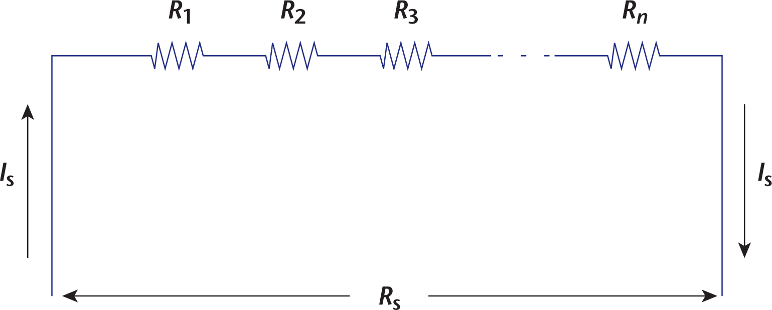
Figure 6.1. Resistors in Series Rs increases as more resistors are added.
As the electrons flow through each resistor, energy is dissipated, and there is a voltage drop associated with each resistor. The voltage drops are additive; that is, for a series of resistors, R1, R2, R3, ⋯ *R**n*, the total voltage drop will be
Vs = V1 + V2 + V3 + ⋯ + *V**n*
Equation 6.9
Because V = IR, we can also see that the resistances of resistors in series are also additive, such that
Rs = R1 + R2 + R3 + ⋯ + *R**n*
Equation 6.10
The set of resistors wired in series can be treated as a single resistor with a resistance equal to the sum of the individual resistances, termed the equivalent or resultant resistance. Note that Rs will always increase as more resistors are added.
KEY CONCEPT
When there is only one path for the current to take, the current will be the same at every point in the line, including through every resistor. Once you know the current of the whole circuit, you can use V = IR to solve for the voltage drop across each resistor (assuming you know the resistances of the resistors).
Example: A circuit is wired with one cell supplying 5 V in series with three resistors of 3 Ω, 5 Ω, and 7 Ω, also wired in series as shown below. What is the resulting voltage across and current through each resistor of this circuit, as well as the entire circuit?
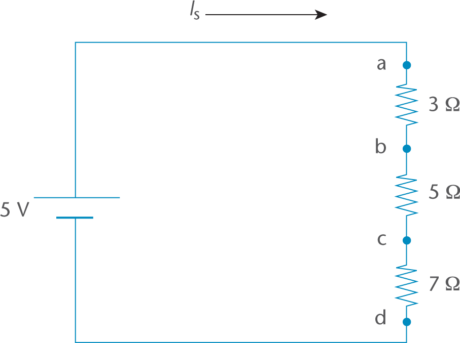
Solution: The total resistance of the resistors is
Rs = R1 + R2 + R3 = 3 Ω + 5 Ω + 7 Ω = 15 Ω
Now use Ohm’s law to get the current through the entire circuit:
Is=VsRs=5 V15 Ω=0.33 A
Because everything is in series, this is also the current through each circuit element. Now, use Ohm’s law for each of the resistors in turn. From a to b, the voltage drop across R1 is
IR1 = (0.33 A)(3 Ω) = 1.0 V
From b to c, the voltage drop across R2 is
IR2 = (0.33 A)(5 Ω) = 1.67 V
From c to d, the voltage drop across R3 is
IR3 = (0.33 A)(7 Ω) = 2.33 V
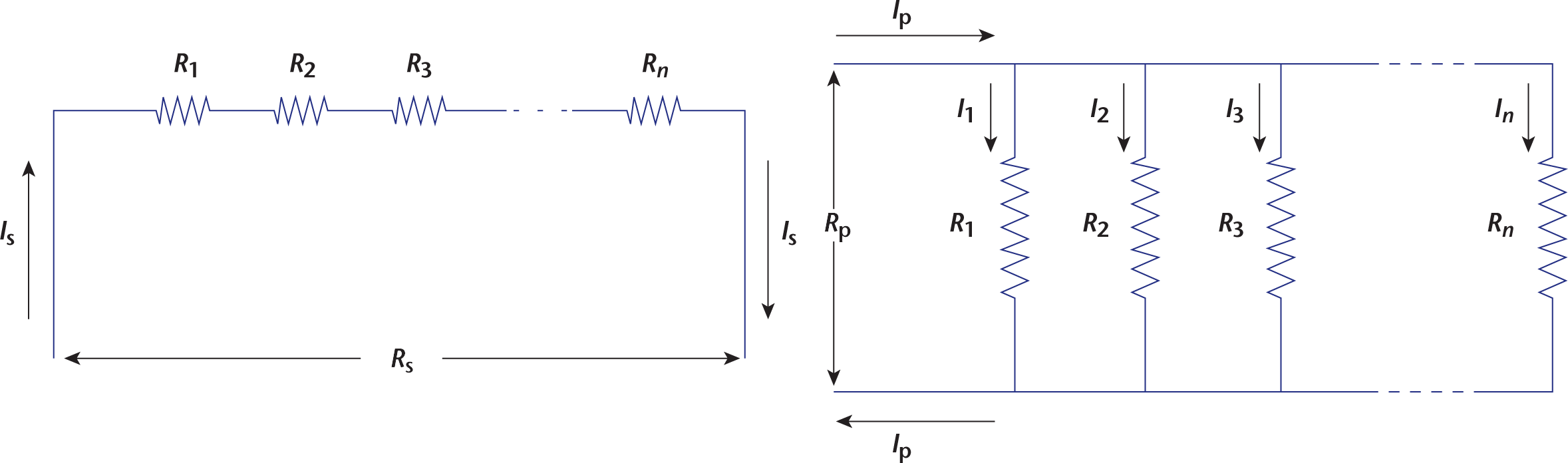
Resistors in Parallel
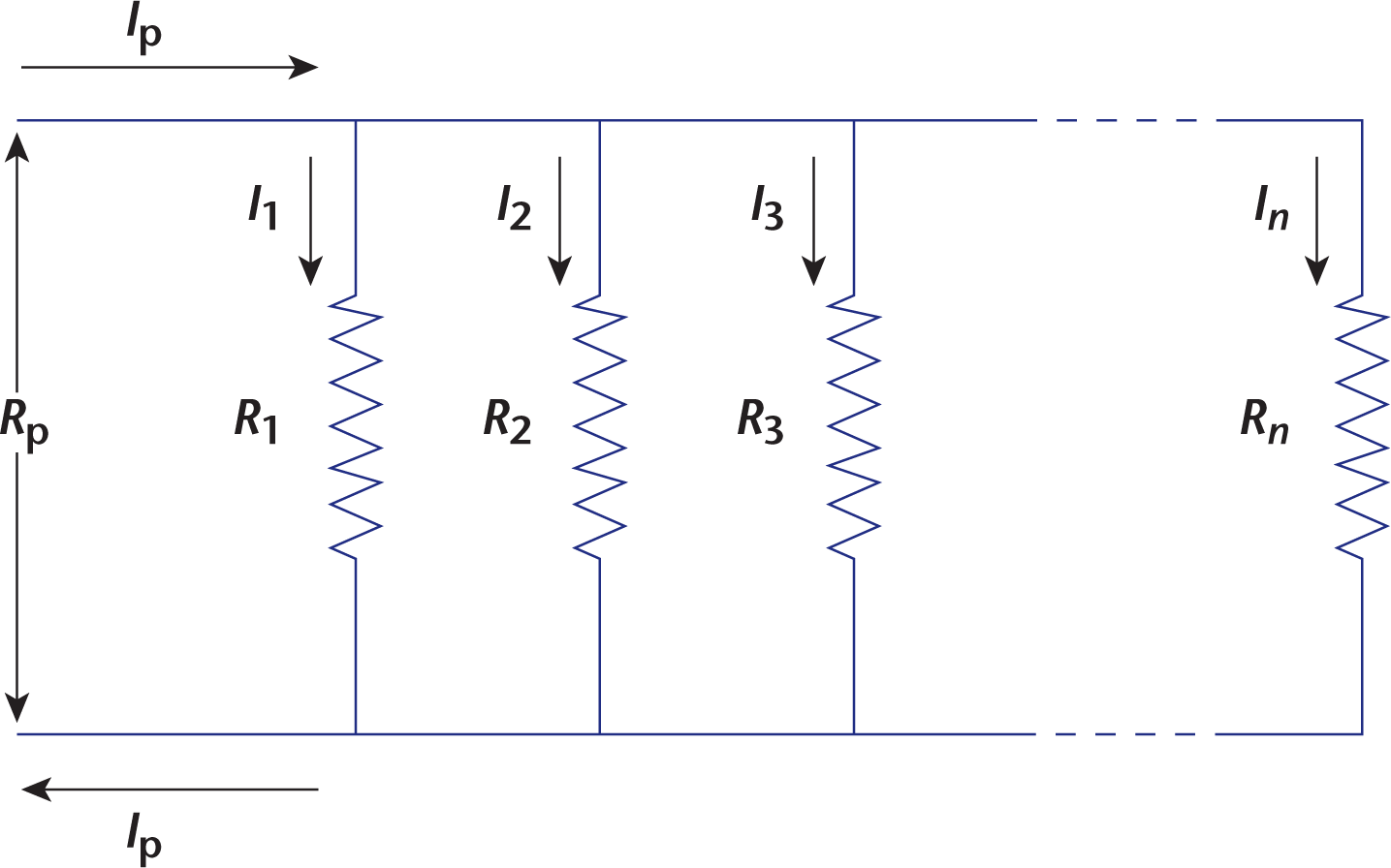
Figure 6.2. Resistors in Parallel Rp decreases as more resistors are added.
When resistors are connected in parallel, they are wired with a common high-potential terminal and a common low-potential terminal, as shown in Figure 6.2. This configuration allows charge to follow different parallel paths between the high-potential terminal and the low-potential terminal. In this arrangement, electrons have a “choice” regarding which path they will take: some will choose one pathway, while others will choose a different pathway. No matter which path is taken, however, the voltage drop experienced by each division of current is the same because all pathways originate from a common point and end at a common point within the circuit. This is analogous to a river that splits into multiple streams before plunging over different waterfalls, which then come back together to re-form the river at a lower height. If all the water starts at some common height and ends at a lower common height, then it doesn’t matter how many “steps” the water fell over to get to the bottom of the falls: the change in height is the same for each stream. In circuits with parallel arrangements of resistors, this is expressed mathematically as:
Vp = V1 = V2 = V3 = ⋯ = *V**n*
Equation 6.11
KEY CONCEPT
Remember Kirchhoff’s loop rule: if every resistor is in parallel, then the voltage drop across each pathway alone must be equal to the voltage of the source.
While the voltage is the same for all parallel pathways, the resistance of each pathway may differ. In this case, electrons prefer the path of least resistance; in other words, the current will be largest through the pathways with the lowest resistance. In fact, there is an inverse relationship between the portion of the current that travels through a particular pathway and the resistance offered by that pathway.
The resistance equation previously discussed shows us that there is an inverse relationship between the cross-sectional area of a resistor and the resistance of that resistor. Like opening up rush-hour lanes to reduce traffic congestion or performing cardiac bypass to perfuse hypoxic heart tissue, the configuration of resistors in parallel allows for a greater total number of conduction paths, and the effect of connecting resistors in parallel is a reduction in the equivalent resistance. In effect, we could replace all resistors in parallel with a single resistor that has a resistance that is less than the resistance of the smallest resistor in the circuit. The equivalent resistance of resistors in parallel is calculated by
1Rp=1R1+1R2+1R3+⋯+1Rn
Equation 6.12
Note that Rp will always decrease as more resistors are added.
Because the voltage drop across any one circuit branch must be same as the voltage drops across each of the other parallel branches, we can see that the magnitude of the current in each branch will be inversely proportional to the resistance offered by each branch. This comes directly from Ohm’s law. Thus, if a circuit divides into two branches and one branch has twice the resistance of the other, the one with twice the resistance will have half the magnitude of current compared to the other. Remember that the sum of the currents going into each division, according to Kirchhoff’s junction rule, must equal the total current going into the point at which the current divides.
Example: Consider two equal resistors wired in parallel. What is the equivalent resistance of the setup?
Solution: The equation for summing resistors in parallel is
1Rp=1R1+1R2
Next, find the common denominator of the right side:
1Rp=R2R1R2+R1R1R2=R1+R2R1R2
Then, take the inverse:
Rp=R1R2R1+R2
This is a special case where R1 = R2. Substituting in, we get:
Rp=R22R=R2
In the example above, we can see that the total resistance is halved by wiring two identical resistors in parallel. More generally, when n identical resistors are wired in parallel, the total resistance is given by Rn. Note that the voltage across each of the parallel resistors is equal and that, for equal resistances, the current flowing through each of the resistors is also equal (that is, a current of Itotaln runs through each).
Example: Consider two resistors wired in parallel with R1 = 5 Ω and R2 = 10 Ω. If the voltage across them is 10 V, what is the current through each of the two resistors?
Solution: First, the current flowing through the whole circuit must be found. To do this, the equivalent resistance must be calculated:
1Rp=1R1+1R2=15 Ω+110 Ω=310 ΩRp=103Ω
Using Ohm’s law to calculate the current flowing through the circuit gives
Ip=VpRp=10 V(103 Ω)=3 A
Three amps flow through the combination of R1 and R2. Because the resistors are in parallel, Vp = V1 = V2 = 10 V. Apply Ohm’s law to each resistor individually:
I1=VpR1=10 V5 Ω=2 AI2=VpR2=10 V10 Ω=1 A
As a check, note that Ip = 3 A = I1 + I2. More current flows through the smaller resistor. In particular, note that R1, with half the resistance of R2, has twice the current. Once Ip was found to be 3 A, the problem could have been solved by noting the ratio of the resistances of the two branches.
MCAT EXPERTISE
When approaching circuit problems, the first things you need to find are the total (circuit) values: the total voltage (almost always given as the voltage of the battery), the total (equivalent) resistance, and the total current. To find the total current, first find the total resistance of the circuit.
MCAT CONCEPT CHECK 6.2
Before you move on, assess your understanding of the material with these questions.
- How does adding or removing a resistor change the total resistance of a circuit with resistors in series? In parallel?
- Series:
_________________________________
- Parallel:
_________________________________
- What four physical quantities determine the resistance of a resistor?
- _________________________________
- _________________________________
- _________________________________
- _________________________________
- How does power relate to current, voltage, and resistance?
_________________________________
- True or False: The internal resistance of a battery will lower the amount of current it can provide.
- A circuit is set up with three resistors. The circuit has one branch through R1, then splits with R2 and R3 set up parallel to each other. If R1 = 3 Ω, R2 = 2 Ω, and R3 = 6 Ω, then what proportion of the total current will travel through each resistor? What will be the total resistance of the circuit?
_________________________________
6.3 Capacitance and Capacitors
LEARNING OBJECTIVES
After Chapter 6.3, you will be able to:
- Predict the behavior of a capacitor when charging and discharging
- Describe the impact of a dielectric on capacitance, voltage, and charge
- Recognize the physical properties that impact capacitance of a capacitor
- Contrast the effects of a capacitor on a circuit in series as compared to a circuit in parallel:

Aside from batteries and resistors, the other major circuit element tested on the MCAT is the capacitor. Capacitors are characterized by their ability to hold charge at a particular voltage. There are excellent real-world examples of capacitors. Perhaps the most important capacitor you’ll encounter in the clinics is the defibrillator. While a defibrillator is charging, a high-pitched electronic tone sounds as electrons build up on the capacitor. When the defibrillator is fully charged, that charge can be released in one surge of power (after the operator yells Clear!). The clouds and the ground during a lightning storm also act as a capacitor, with the charge building up between them eventually discharging as a bolt of lightning. The MCAT focuses on a particular type of capacitor called a parallel plate capacitor, and all of our discussion will center on capacitors of this type.
Properties of Capacitors
When two electrically neutral metal plates are connected to a voltage source, positive charge builds up on the plate connected to the positive (higher potential) terminal, and negative charge builds up on the plate connected to the negative (lower potential) terminal. The two-plate system is a capacitor because it can store a particular amount of charge at a particular voltage. The capacitance of a capacitor is defined as the ratio of the magnitude of the charge stored on one plate to the potential difference (voltage) across the capacitor. Therefore, if a voltage V is applied across the plates of a capacitor and a charge Q collects on it (with +Q on the positive plate and –Q on the negative plate), then the capacitance is given by
C=QV
Equation 6.13
The SI unit for capacitance is the farad (1 F=1 CV). Because one coulomb is such a large quantity of charge, one farad is a very large capacitance. Capacitances are usually given in microfarads (1 μF = 1 × 10⁻⁶ F) or picofarads (1 pF = 1 × 10–12 F). Be careful not to confuse the farad with the Faraday constant from electrochemistry, F, which is the amount of charge in one mole of electrons (96,485 Cmol e−).
The capacitance of a parallel plate capacitor is dependent upon the geometry of the two conduction surfaces. For the simple case of the parallel plate capacitor, the capacitance is given by
C=ε0(Ad)
Equation 6.14
where ε0 is the permittivity of free space (8.85×10⁻¹² Fm). A is the area of overlap of the two plates, and d is the separation of the two plates. The separation of charges sets up a uniform electric field between the plates with parallel field vectors, the magnitude of which can be calculated as
E=Vd
Equation 6.15
KEY CONCEPT
If you look back to the equations discussed in Chapter 5 of MCAT Physics and Math Review, you can see that the equation for E here can be derived from the other fundamental electrostatics equations. If V=kQr and E=kQr2, then V = E × r. **In this setup, r is the distance between the plates, d, so we can rewrite this as V = Ed.
The direction of the electric field at any point between the plates is from the positive plate toward the negative plate. If we imagine placing a positively charged particle between the oppositely charged plates, we would expect the particle to accelerate in that same direction. This should not be surprising, as electric field lines always point in the direction that indicates the direction of a force exerted on a positive charge.
Regardless of the particular geometry of a capacitor (parallel plate or otherwise), the function of a capacitor is to store an amount of energy in the form of charge separation at a particular voltage. This is akin to the function of a dam, the purpose of which is to store gravitational potential energy by holding back a mass of water at a given height. The potential energy stored in a capacitor is
U=12 CV2
Equation 6.16
Dielectric Materials
The term dielectric material is just another way of saying insulation. When a dielectric material, such as air, glass, plastic, ceramic, or certain metal oxides, is introduced between the plates of a capacitor, it increases the capacitance by a factor called the dielectric constant (κ). The dielectric constant of a material is a measure of its insulating ability, and a vacuum has a dielectric constant of 1, by definition. For reference, the dielectric constant of air is just slightly above 1, glass is 4.7, and rubber is 7. These numbers need not be memorized; any relevant dielectric constants will be given on Test Day.
The capacitance due to a dielectric material is
C′ = κC
Equation 6.17
where C′ is the new capacitance with the dielectric present and C is the original capacitance.
MNEMONIC
Incorporating the dielectric constant into Equation 6.14 reveals that capacitors are CAκεd with charge (C = Aκε0/d).
KEY CONCEPT
A dielectric material can never decrease the capacitance; thus, κ can never be less than 1.
Dielectrics in Isolated Capacitors
When a dielectric material is placed in an isolated, charged capacitor—that is, a charged capacitor disconnected from any circuit—the voltage across the capacitor decreases. This is the result of the dielectric material shielding the opposite charges from each other. By lowering the voltage across a charged capacitor, the dielectric has increased the capacitance of the capacitor by a factor of the dielectric constant. Thus, when a dielectric material is introduced into an isolated capacitor, the increase in capacitance arises from a decrease in voltage.
Dielectrics in Circuit Capacitors
When a dielectric material is placed in a charged capacitor within a circuit—that is, still connected to a voltage source—the charge on the capacitor increases. The voltage must remain constant because it must be equal to that of the voltage source. By increasing the amount of charge stored on the capacitor, the dielectric has increased the capacitance of the capacitor by a factor of the dielectric constant. Thus, when a dielectric material is introduced into a circuit capacitor, the increase in capacitance arises from an increase in stored charge.
The stored energy in a capacitor is only useful if it is allowed to discharge. The charge can be released from the plates either by discharging across the plates or through some conductive material with which the plates are in contact. For example, capacitors can discharge into wires, causing a current to pass through the wires in much the same way that batteries cause current to move through a circuit. The paddles of the defibrillator machine, once charged, are placed on either side of a patient’s heart that has gone into a life-threatening arrhythmia (such as ventricular fibrillation). The reason the doctor yells Clear! before discharging the paddles is because the current needs to travel through the patient’s heart—not through any other people who might be touching the patient and creating a parallel pathway. On a much larger scale, lightning occurs when a very, very large amount of charge exceeds the capacitance of the Earth’s surface and the underside of the cloud (the two serving, approximately, as a parallel plate capacitor). The large rapid discharge across the plates of a capacitor is termed a failure of the capacitor, while creating a current through the attached wires is the normal function of a capacitor.
Example: The voltage across the terminals of an isolated 3 µF capacitor is 4 V. If a piece of ceramic having dielectric constant κ = 2 is placed between the plates, find the new charge, capacitance, and voltage of the capacitor.
Solution: The introduction of a dielectric by itself has no effect on the charge stored on the isolated capacitor. There is no new charge, so the charge is the same as before. The charge stored is therefore given by
Q′ = Q = CV = (3 µF)(4 V) = 12 µC
By introducing a dielectric with a dielectric constant of 2, the capacitance of the capacitor is multiplied by 2 (C′ = κC). Hence, the new capacitance is 6 µF.
Now, the new voltage across the capacitor can be determined:
V′=Q′C′=12 μC6 μF=2 V
Example: A 3 µF capacitor is connected to a 4 V battery. If a piece of ceramic having dielectric constant κ = 2 is placed between the plates, find the new charge, capacitance, and voltage of the capacitor.
Solution: This question is very similar to the previous one, but the voltage is held constant here by a battery. Thus, the new voltage is still 4 V.
By introducing a dielectric with a dielectric constant of 2, the capacitance of the capacitor is multiplied by 2 (C′ = κC). Hence, the new capacitance is 6 µF.
Now, the new charge on the capacitor can be determined:
Q′ = C′V′ = (6 µF)(4 V) = 24 µC
Capacitors in Series and Parallel
Just like resistors, capacitors can be arranged within a circuit either in parallel or in series. They can also be arranged with resistors, although this is beyond the scope of the MCAT in most cases.
Capacitors in Series
When capacitors are connected in series, the total capacitance decreases in similar fashion to the decreases in resistance seen in parallel resistors, as shown in Figure 6.3.
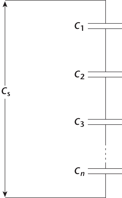
Figure 6.3. Capacitors in Series Cs decreases as more capacitors are added.
This is because the capacitors must share the voltage drop in the loop and therefore cannot store as much charge. Functionally, a group of capacitors in series acts like one equivalent capacitor with a much larger distance between its plates (in fact, with a distance equal to those of each of the series capacitors added together). This increase in distance, as seen earlier, means a smaller capacitance.
Rather than memorizing the following equations independently, understand the conceptual basis for the mathematics of resistors in series and in parallel, and then simply reverse that mathematical approach for capacitors. The equation for calculating the equivalent capacitance for capacitors in series is
1Cs=1C1+1C2+1C3+⋯+1Cn
Equation 6.18
which shows that Cs decreases as more capacitors are added. Note that for capacitors in series, the total voltage is the sum of the individual voltages, just like resistors in series.
Capacitors in Parallel
Capacitors wired in parallel, shown in Figure 6.4, produce a resultant capacitance that is equal to the sum of the individual capacitances.
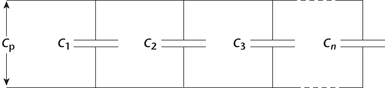
Figure 6.4. Capacitors in Parallel Cp increases as more capacitors are added.
Therefore, Cp increases as more capacitors are added:
Cp = C1 + C2 + C3 + ⋯ + *C**n*
Equation 6.19
Just as we saw with resistors in parallel, the voltage across each parallel capacitor is the same and is equal to the voltage across the source.
MCAT CONCEPT CHECK 6.3
Before you move on, assess your understanding of the material with these questions.
- Assuming the plates are attached by a conducting material, how does a capacitor behave after the voltage source has been removed from a circuit?
_________________________________
- How does a dielectric material impact capacitance? Voltage? Charge?
- Capacitance:
_________________________________
- Voltage:
_________________________________
- Charge:
_________________________________
- How does adding or removing a capacitor change the total capacitance of a circuit with capacitors in series? In parallel?
- Series:
_________________________________
- Parallel:
_________________________________
- What physical qualities contribute to the capacitance of a capacitor?
_________________________________
6.4 Meters
LEARNING OBJECTIVES
After Chapter 6.4, you will be able to:
- Recall key details about ammeters, voltmeters, and ohmmeters, including what they measure, where they should be placed in a circuit, and their ideal resistances
- Determine whether multiple meters should be placed together in a circuit
Although we’ve been focused on calculations of hypothetical circuits so far, it’s important for us to spend some time considering real ones. While we will not analyze any complex circuits here, it is important to be familiar with meters, the devices that are used to measure circuit quantities in the real world.
Ammeters
Ammeters are used to measure the current at some point within a circuit. Using an ammeter requires the circuit to be on, or the current will be 0 A. Ammeters are inserted in series where the current is being measured and use the magnetic properties of a current-carrying wire to cause a visible needle movement or a calibrated display of the current. If there is a particularly high current, this will overwhelm the ammeter, and a special low resistance shunt is used in parallel with the ammeter to allow a reading. Ideally, an ammeter will not change circuit mathematics when it is inserted into the circuit. To do so, it must have an extremely low resistance. Ideal ammeters have zero resistance and no voltage drop across themselves.
Voltmeters
A voltmeter, like an ammeter, requires a circuit to be active. Voltmeters also use magnetic properties of current-carrying wires. However, voltmeters are used to measure the voltage drop across two points in a circuit. They are wired in parallel to these two points. Because the goal with any meter is to minimize its impact on the rest of the circuit, and voltmeters are wired in parallel, an ideal voltmeter has infinite resistance.
Ohmmeters
Unlike voltmeters and ammeters, an ohmmeter does not require a circuit to be active (in fact, some ohmmeters will give false readings or can be damaged by an active circuit). Ohmmeters will often have their own battery of known voltage and then function as ammeters through another point in the circuit. Because only one circuit element is being analyzed, Ohm’s law can be used to calculate resistance by knowing the ohmmeter’s voltage and the current created through another point in the circuit.
MCAT CONCEPT CHECK 6.4
Before you move on, assess your understanding of the material with these questions.
- What do each of the following types of meters measure? Where are they placed in circuits? What are their ideal resistances?
Meter Type Measures… Placement Ideal Resistance Ammeter Voltmeter Ohmmeter
- True or False: A voltmeter and an ammeter should not be placed in the same circuit.
Conclusion
This chapter covered a lot of material. We began with a review of current, taking special note of the conventional definition of current as the movement of positive charge (when, in fact, negatively charged electrons are actually moving). We considered the basic laws of electricity and circuits: Kirchhoff’s laws, which are expressions of conservation of charge and energy, and Ohm’s law, which relates voltage, current, and resistance. We defined resistance and analyzed the relationships between resistance and resistivity (directly proportional), resistance and length (directly proportional), and resistance and cross-sectional area (inversely proportional). We also defined capacitance as the ability to store charge at some voltage, thereby storing energy. Throughout, we stressed the importance of the both the conceptual and mathematical treatment of resistors and capacitors in series and in parallel as a major testing topic on the MCAT. Finally, we covered the different meters that can be used to measure circuit quantities.
Electricity is often a challenging concept for MCAT students. Unlike kinematics, thermodynamics, and fluids, which are often more tangible, electricity is often best understood through schematics and models. Take time to review these last two chapters, as they will assuredly pay off as points on Test Day. In the next chapter, we turn our attention to a completely different topic that is no more tangible—but is far more audible: sound.
GO ONLINE
You’ve reviewed the content, now test your knowledge and critical thinking skills by completing a test-like passage set in your online resources!
CONCEPT SUMMARY
Current
- Current is the movement of charge that occurs between two points that have different electrical potentials.
- By convention, current is defined as the movement of positive charge from the high-potential end of a voltage source to the low-potential end.
- In reality, it is negatively charged particles (electrons) that move in a circuit, from low potential to high potential.
- Current flows only in conductive materials.
- Metallic conduction relies on uniform movement of free electrons in metallic bonds.
- Electrolytic conduction relies on the ion concentration of a solution.
- Insulators are materials that do not conduct a current.
- Kirchhoff’s laws express conservation of charge and energy.
- Kirchhoff’s junction rule states that the sum of currents directed into a point within a circuit equals the sum of the currents directed away from that point.
- Kirchhoff’s loop rule states that in a closed loop, the sum of voltage sources is always equal to the sum of voltage drops.
Resistance
- Resistance is opposition to the movement of electrons through a material.
- Resistors are conductive materials with a moderate amount of resistance that slow down electrons without stopping them.
- Resistance is calculated using the resistivity, length, and cross-sectional area of the material in question.
- Ohm’s law states that for a given resistance, the magnitude of the current through a resistor is proportional to the voltage drop across the resistor.
- Resistors in circuits can be combined to calculate the equivalent resistance of a full or partial circuit.
- Resistors in series are additive and sum together to create the total resistance of a circuit.
- Resistors in parallel cause a decrease in equivalent resistance of a circuit.
- Across each resistor in a circuit, a certain amount of power is dissipated, which is dependent on the current through the resistor and the voltage drop across the resistor.
Capacitance and Capacitors
- Capacitors have the ability to store and discharge electrical potential energy.
- Capacitance in parallel plate capacitors is determined by the area of the plates and the distance between the plates.
- Capacitors in series cause a decrease in the equivalent capacitance of a circuit.
- Capacitors in parallel sum together to create a larger equivalent capacitance.
- Dielectric materials are insulators placed between the plates of a capacitor that increase capacitance by a factor equal to the material’s dielectric constant, κ.
Meters
- Ammeters are inserted in series in a circuit to measure current; they have negligible resistance.
- Voltmeters are inserted in parallel in a circuit to measure a voltage drop; they have very large resistances.
- Ohmmeters are inserted around a resistive element to measure resistance; they are self-powered and have negligible resistance.
ANSWERS TO CONCEPT CHECKS
**6.1**
- Current is the movement of positive charge through a conductive material over time and is given in ampères (Cs). Voltage is a potential difference between two points and is given in volts (JC). Electromotive force (emf) refers to the potential difference of the voltage source for a circuit, usually a battery, and is given in volts. Conductivity is the reciprocal of resistance and is a measure of permissiveness to current flow; it is measured in siemens (S).
- The sodium chloride solution likely has a higher conductivity because it is a salt and will increase the ion content of water. Glucose does not dissociate, and therefore it has a near-zero impact on conductivity.
- True. This is a restatement of Kirchhoff’s junction rule.
- False. While the voltage sources and voltage drops are equal in any closed loop, this is not necessarily true for the entire circuit. For example, a 9 V battery that powers 10 light bulbs in parallel has a 9 V voltage source and a 9 V drop across each light bulb—a total of 90 V of drop across all of the light bulbs combined.
**6.2**
- Adding a resistor in series increases the total resistance of a circuit; removing one in series decreases the total resistance in the circuit. These relationships are reversed in parallel: adding a resistor decreases resistance while removing one increases it.
- Resistivity, length, cross-sectional area, and temperature all contribute to the resistance of a resistor.
- Power is related to current, voltage, and resistance through the equations P=IV=I2R=V2R.
- True. The internal resistance will lower the available voltage for the circuit. Lowering the available voltage will also lower current for any given resistance.
- All current must travel through the first resistor, regardless of its resistance. Since the ratio of resistance for R2:R3 is 1:3, the ratio of current passing through them will be 3:1. In other words, 34 of the current will pass through R2 while 14 of the current will pass through R3. To calculate the total resistance, first calculate the resistance of the resistors in parallel: 1R2+3=12+16=23→R2+3=1.5 Ω. Add this to the resistance of R1 to get the total resistance: 4.5 Ω.
**6.3**
- The capacitor discharges, providing a current in the opposite direction of the initial current.
- A dielectric material will always increase capacitance. If the capacitor is isolated, its voltage will decrease when a dielectric material is introduced; if it is in a circuit, its voltage is constant because it is dictated by the voltage source. If a capacitor is isolated, the stored charge will remain constant because there is no additional source of charge; if it is in a circuit, the stored charge will increase.
- Adding a capacitor in series decreases the total capacitance of a circuit; removing one in series increases the total capacitance in the circuit. These relationships are reversed in parallel: adding a capacitor increases capacitance while removing one decreases it.
- Surface area, distance, and dielectric constant all contribute to the capacitance of a capacitor.
**6.4**
-
Meter Type Measures… Placement Ideal Resistance Ammeter Current In series with point of interest 0
Voltmeter Potential difference (voltage) Parallel with circuit element of interest ∞
Ohmmeter Resistance Two points in series with circuit element of interest 0
- False. Voltmeters and ammeters are designed to have minimum impact on a circuit; thus, they can be used together.
SCIENCE MASTERY ASSESSMENT EXPLANATIONS
1. B
Electrical current is defined as charge flow, or in mathematical terms, charge transferred per time: I=QΔt. A 15 A current that acts for 0.1 s will transfer 15 A × 0.1 s = 1.5 C of charge.
2. D
To measure the current at any point in a circuit, an ammeter should be placed in series. If placed in parallel, a new path for current would be created, so the measured value would not be reflective of actual current in the circuit. This observation matches (D). Note that an ideal ammeter should have zero resistance so that it has no effect on the current of the circuit.
3. B
The resistance of a resistor is given by the formula R=ρLA Thus, there is a direct proportionality between resistance and resistivity. Because the other variables are equal between the two resistors, we can determine that if R1:R2 is a 1:2 ratio, then ρ1: ρ2 is also a 1:2 ratio.
4. D
This question tests our understanding of batteries in a circuit. The voltage across the terminals of the battery when there is no current flowing is referred to as the electromotive force (emf or ε of the battery). However, when a current is flowing through the circuit, the voltage across the terminals of the battery is decreased by an amount equal to the current multiplied by the internal resistance of the battery. Mathematically, this is given by the equation
V = ε – irint
To determine the emf of the battery, first calculate the voltage across the battery when the current is flowing. For this, we can use Ohm’s law:
V=IR=(0.5 A)(3 Ω)=1.5 V
Because we know the internal resistance of the battery, the current, and the voltage, we can calculate the emf:
ε=V+irint=1.5 V+(0.5 A)(0.1 Ω)=1.5+0.05=1.55 V
The answer makes sense in the context of a real battery because its internal resistance is supposed to be very small so that the voltage provided to the circuit is as close as possible to the emf of the cell when there is no current running.
5. A
We are told that transformers conserve energy so that the output power equals the input power. Thus, Pout = Pin, or IoutVout = IinVin. There is therefore an inverse proportionality between current and voltage. If the output voltage is 300% of the input voltage (3 times its amount), then the output current must be 13 of the input voltage. This can be represented as a 1:3 ratio.
6. B
The fastest way to tackle these kinds of questions is to simplify the circuit bit by bit. For example, notice that R3 and R4 are in parallel with each other and are in series with R2; similarly, R5 and R6 are in series. If we determine the total resistance in each branch, we will be left with three branches in parallel. To start, find the total resistance in the middle branch:
1R3 + 4=1R3+1R4=132Ω+132Ω→R3 + 4=16ΩR2 + 3 + 4=R2+R3 + 4=4Ω+16Ω=20Ω
Next, take a look at the total resistance in the bottom branch:
R5+6 = R5 + R6 = 15 Ω + 5 Ω = 20 Ω
The circuit can now be viewed as three resistors in parallel, each providing a resistance of 20 Ω. The total resistance in the circuit is thus
1Rtot=1R1+1R2 + 3 + 4+1R5 + 6=120 Ω+120 Ω+120 Ω→203 Ω=6.67 Ω
7. A
To determine the moles of charge that pass through the circuit over a period of 10 s, we will have to calculate the amount of charge running through the circuit. Charge is simply current multiplied by time, and the current can be calculated using Ohm’s law:
V=IRandI=QΔt→Q=VΔtRQ=(100 V)(10 s)2 Ω=500 C
Then, calculate the number of moles of charge that this represents by using the Faraday constant and approximating F as 105Cmol e−:
(500 C) [mol e−105 C]=5×10⁻³ mol e−
This is closest to (A).
8. C
To determine the voltage drop across the 23Ω resistor, start by calculating the total resistance in the circuit. For the resistors in parallel, the equivalent resistance is
1Rp = 12 Ω+32 Ω→Rp =12Ω
The total resistance in the circuit is the sum of the remaining resistor and the equivalent resistance of the other two:
Rs = 12Ω+12Ω = 1 Ω
Now that we know the equivalent resistance, we can calculate the total current using Ohm’s law:
I=VR=10 V1 Ω=10 A
Finally, we can determine the voltage drop across the parallel resistors. The voltage drop across the 12Ω resistor must be (10 A)(12 Ω)=5 V. Therefore, there must be a 5 V drop across both the 23 Ω resistor and 2 Ω resistor, according to Kirchhoff’s loop rule. Each of these resistors forms a complete loop in combination with the 12 Ω resistor and 10 V voltage source, and the net potential difference around any closed loop must be 0 V.
9. D
This question should bring to mind the equation C=ε0(Ad), where ε0 is the permittivity of free space, A is the area of the plates, and d is the distance between the plates. From this equation, we can infer that doubling the area will double the capacitance, and halving the distance will also double the capacitance. Therefore, the new capacitance is four times larger than the initial capacitance.
10. C
Because the question is asking us to calculate the charge on the capacitor, use the formula Q = CV. We are given V = 7500 V and can calculate C from the formula for energy, U=12 CV2:
U=12 CV2=12(QV)V2=QV2Q=2 UV=2(400 J)7500 V≈8008000=0.1 C
Thus, the charge is close to 0.1 C, which is closest to (C).
11. C
Power is energy dissipated per unit time; therefore, the energy dissipated is E = PΔt. In the five-second interval during which the resistor is active, it has a 2 A current for three of those seconds. The power dissipated by a resistor R carrying a current I is P = I2R. Therefore, the energy dissipated is
E = I2RΔt = (2 A)2(10 Ω)(3 s) = 4 × 10 × 3 = 120 J
12. A
Kirchhoff’s junction rule states that the sum of all currents directed into a point is always equal to the sum of all currents directed out of the point. The currents directed into point P are 8 A, 2 A, and 3 A, so the sum is 13 A. The currents directed out of point P are 5 A and 6 A, so the total is 11 A. Because the two numbers must always be equal, an additional current of 2 A must be directed away from point P toward point x.
13. D
The electric field between two plates of a parallel plate capacitor is related to the potential difference between the plates of the capacitor and the distance between the plates, as shown in the formula E=Vd. The addition of another battery will increase the total voltage applied to the circuit, which, consequently, will increase the electric field. The addition of a resistor in series will increase the resistance and decrease the voltage applied to the capacitor, eliminating (A). Adding a resistor in parallel will not change the voltage drop across the capacitor and should not change the electric field, eliminating (B). Increasing the distance between the plates, (C), would decrease the electric field, not increase it.
14. D
The resistance of the three resistors wired in series is equal to the sum of the individual resistances (12 Ω). This means that the circuit functionally contains a 12 Ω resistor and a 4 Ω resistor in parallel. To determine the overall resistance of this system, use the formula
1Rp=1R1+1R2=112 Ω+14 Ω=1 + 312 Ω→Rp=3 Ω
15. C
While this is primarily a recall question, it should also be intuitive. Voltmeters are attempting to determine a change in potential from one point to another. To do this, they should not provide an alternate route for charge flow and should therefore have infinite resistance. Ammeters attempt to determine the flow of charge at a single point and should not contribute to the resistance of a series circuit; therefore, they should have no resistance.
GO ONLINE
Consult your online resources for additional practice.
EQUATIONS TO REMEMBER
(6.1) Current: I=QΔt
(6.2) Kirchhoff’s junction rule: Iinto junction = Ileaving junction
(6.3) Kirchhoff’s loop rule: Vsource = Vdrop
(6.4) Definition of resistance: R=ρLA
(6.5) Ohm’s law: V = IR
(6.6) Voltage and cell emf: V = Ecell – irint
(6.7) Definition of power: P=Wt=ΔEt
(6.8) Electric power: P=IV=I2R=V2R
(6.9) Voltage drop across circuit elements (series): Vs = V1 + V2 + V3 + ⋯ + *V**n*
(6.10) Equivalent resistance (series): Rs = R1 + R2 + R3 + ⋯ + *R**n*
(6.11) Voltage drop across circuit elements (parallel): Vp = V1 = V2 = V3 = ⋯ = *V**n*
(6.12) Equivalent resistance (parallel): 1Rp=1R1+1R2+1R3+⋯+1Rn
(6.13) Definition of capacitance: C=QV
(6.14) Capacitance based on parallel plate geometry: C=ε0(Ad)
(6.15) Electric field in a capacitor: E=Vd
(6.16) Potential energy of a capacitor: U=12 CV2
(6.17) Capacitance with a dielectric material: C′ = κC
(6.18) Equivalent capacitance (series): 1Cs=1C1+1C2+1C3+⋯+1Cn
(6.19) Equivalent capacitance (parallel): Cp = C1 + C2 + C3 + ⋯ + Cn
SHARED CONCEPTS
Biology Chapter 6
The Respiratory System
Biology Chapter 7
The Cardiovascular System
General Chemistry Chapter 12
Electrochemistry
Physics and Math Chapter 2
Work and Energy
Physics and Math Chapter 4
Fluids
Physics and Math Chapter 5
Electrostatics and Magnetism