Chapter 8: Light and Optics

Chapter 8: Light and Optics
Science Mastery Assessment
Every pre-med knows this feeling: there is so much content I have to know for the MCAT! How do I know what to do first or what’s important?
While the high-yield badges throughout this book will help you identify the most important topics, this Science Mastery Assessment is another tool in your MCAT prep arsenal. This quiz (which can also be taken in your online resources) and the guidance below will help ensure that you are spending the appropriate amount of time on this chapter based on your personal strengths and weaknesses. Don’t worry though— skipping something now does not mean you’ll never study it. Later on in your prep, as you complete full-length tests, you’ll uncover specific pieces of content that you need to review and can come back to these chapters as appropriate.
How to Use This Assessment
If you answer 0–7 questions correctly:
Spend about 1 hour to read this chapter in full and take limited notes throughout. Follow up by reviewing all quiz questions to ensure that you now understand how to solve each one.
If you answer 8–11 questions correctly:
Spend 20–40 minutes reviewing the quiz questions. Beginning with the questions you missed, read and take notes on the corresponding subchapters. For questions you answered correctly, ensure your thinking matches that of the explanation and you understand why each choice was correct or incorrect.
If you answer 12–15 questions correctly:
Spend less than 20 minutes reviewing all questions from the quiz. If you missed any, then include a quick read-through of the corresponding subchapters, or even just the relevant content within a subchapter, as part of your question review. For questions you got correct, ensure your thinking matches that of the explanation and review the Concept Summary at the end of the chapter.
- If a light ray has a frequency of 5.0 × 10¹⁴ Hz, in which region of the electromagnetic spectrum is it located?
- X-ray
- UV
- Visible
- Infrared
- During the fall, the leaves of some trees change in color from green to red because chlorophyll breaks down, leaving the secondary anthocyanin pigments. Which of the following best describes the light reflected by anthocyanin?
- Has a wavelength of 700 m
- Has a wavelength of 580 nm
- Has a frequency of 4.2 × 10⁶ Hz
- Has a frequency of 4.2 × 10¹³ Hz
- An object is placed at the center of curvature of a concave mirror. Which of the following is true about the image?
- It is real and inverted.
- It is virtual and inverted.
- It is real and upright.
- It is virtual and upright.
- In a double slit experiment, what wavelength of light must be used for the second dark fringe to be at an angle of 30° given that the distance between the two slits is 0.3 mm?
- 1 × 10⁻⁵ m
- 6 × 10⁻⁵ m
- 3.6 × 10⁻² m
- 6 × 10⁻² m
- A ray of light (f = 5 × 10¹⁴ Hz) travels from air into crystal into chromium. If the indices of refraction of air, crystal, and chromium are 1, 2, and 3, respectively, and the incident angle is 30°, then which of the following describes the frequency and the angle of refraction in the chromium?
- 5 × 10¹⁴ Hz; 9.6°
- 5 × 10¹⁴ Hz; 57°
- 1.0 × 10¹⁰ Hz; 9.6°
- 1.0 × 10¹⁰ Hz; 57°
- A source of light (f = 6.0 × 10¹⁴ Hz) passes through three plane polarizers. The first two polarizers are in the same direction, while the third is rotated 90° with respect to the second polarizer. What is the frequency of the light that comes out of the third polarizer?
- 3.0 × 10¹⁴ Hz
- 6.0 × 10¹⁴ Hz
- 9.0 × 10¹⁴ Hz
- Light will not pass through the third polarizer
- As part of an organic chemistry lab, a student must determine the specific rotation of a chiral product. The student uses a plane polarizer, but accidentally inserts a second polarizer at a 90° angle to the first. What is true of the resulting light if it passes through both polarizers?
- It is circularly polarized.
- It is twice as plane polarized.
- There is no light.
- It is the same as when passed through a single polarizer.
- Which of the following describes the image formed by an object placed in front of a convex lens at a distance smaller than the focal length?
- Virtual and inverted
- Virtual and upright
- Real and upright
- Real and inverted
- A submarine is inspecting the surface of the water with a laser that points from the submarine to the surface of the water and through the air. At what angle will the laser not penetrate the surface of the water but rather reflect entirely back into the water? (Assume nwater = 1.33 and nair = 1.)
- 19°
- 29°
- 39°
- 49°
- A student is analyzing the behavior of a light ray that is passed through a small opening and a lens and allowed to project on a screen a distance away. What happens to the central maximum (the brightest spot on the screen) when the slit becomes narrower?
- The central maximum remains the same.
- The central maximum becomes narrower.
- The central maximum becomes wider.
- The central maximum divides into smaller light fringes.
- Which of the following are able to produce a virtual image?
- Convex lens
- Concave lens
- Plane mirror
- I only
- III only
- II and III only
- I, II, and III
- Monochromatic red light is allowed to pass between two different media. If the incident angle in medium 1 is 30° and the incident angle in medium 2 is 45°, what is the relationship between the speed of the light in medium 2 compared to that in medium 1?
- ν2=ν12
- ν22=ν1
- ν2=ν13
- ν23=ν1
- A scientist looks through a microscope with two thin lenses with m1 = 10 and m2 = 40. What is the overall magnification of this microscope?
- 0.25
- 30
- 50
- 400
- Imagine that a beam of monochromatic light originates in air and is allowed to shine upon the flat surface of a piece of glass at an angle of 60° with the normal. The reflected and refracted beams are perpendicular to each other. What is the index of refraction of the glass?
- 33
- 1
- 2
- 3
- Which of the following will not result in the splitting of white light into its component colors?
- Dispersion through a prism
- Diffraction through a grating
- Refraction within a thin film
- Reflection from an ideal convex mirror
Answer Key
- C
- D
- A
- B
- A
- D
- C
- B
- D
- C
- D
- A
- D
- D
- D
Chapter 8: Light and Optics
CHAPTER 8
LIGHT AND OPTICS
In This Chapter
8.1 Electromagnetic Spectrum
Electromagnetic Waves
Color and the Visible Spectrum
8.2 Geometrical Optics
Reflection
Refraction
Lenses
Dispersion
8.3 Diffraction
Single Slit
Slit–Lens System
Multiple Slits
X-Ray Diffraction
8.4 Polarization
Plane-Polarized Light
Circular Polarization
Concept Summary
CHAPTER PROFILE
The content in this chapter should be relevant to about 14% of all questions about physics on the MCAT.
This chapter covers material from the following AAMC content category:
4D: How light and sound interact with matter
Introduction
The next time you’re browsing your local convenience store, take a look at the security mirrors—the ones that bulge out from the wall, usually above eye level. Looking into one of these mirrors, notice not just that the image you see of the world is distorted but how it is distorted: the image is still right-side up, but everything is much smaller than you’d expect, and the curve of the mirror introduces some slopes that are not present in reality. Additionally, you see a much wider field of vision than you would if the mirror were a simple plane mirror. This is why security mirrors are useful: they are a convenient, low-tech solution that allows the cashier to survey the entire store in one glance. All these features result from the fact that the security mirror is a convex, diverging optical system. Parallel light rays that hit the mirror are reflected in multiple directions, which allows observers to see a large field of vision, even if the image is somewhat distorted and the objects in the image are closer than they appear. Indeed, the passenger-side mirror of a car that bears that same message is also a convex mirror, allowing the driver to see a wider view of the other vehicles behind the car.
This chapter will first complete a topic from Chapter 7 of MCAT Physics and Math Review by analyzing the transverse waveform of visible light and other electromagnetic (EM) waves. We will then consider in detail the rules of optics, which describe the behavior of electromagnetic waves as they bounce off of and travel through various shapes and compositions of matter. The optical systems covered are those tested on the MCAT: concave and convex mirrors, which produce images by reflection, and concave and convex lenses, which produce images by refraction. To finish, we will discuss the phenomena of thin-slit experiments (diffraction) and light polarization.
8.1 Electromagnetic Spectrum
LEARNING OBJECTIVES
After Chapter 8.1, you will be able to:
- Order the types of electromagnetic radiation, such as x-rays, microwaves, and visible light, from lowest to highest energy
- Describe the properties of electromagnetic waves
- Compare the visible spectrum to the full electromagnetic spectrum
The full electromagnetic spectrum includes radio waves on one end (long wavelength, low frequency, low energy) and gamma rays on the other (short wavelength, high frequency, high energy). Between the two extremes, we find, in order from lowest energy to highest energy, microwaves, infrared, visible light, ultraviolet, and x-rays. This chapter will focus primarily on the range of wavelengths corresponding to the visible spectrum of light (400 nm to 700 nm).
Electromagnetic Waves
A changing magnetic field can cause a change in an electric field, and a changing electric field can cause a change in a magnetic field. Because of the reciprocating nature of these two fields, we can see how electromagnetic waves occur in nature. Each oscillating field causes oscillations in the other field completely independent of matter, so electromagnetic waves can even travel through a vacuum.
Electromagnetic waves are transverse waves because the oscillating electric and magnetic field vectors are perpendicular to the direction of propagation. The electric field and the magnetic field are also perpendicular to each other. This is illustrated in Figure 8.1.
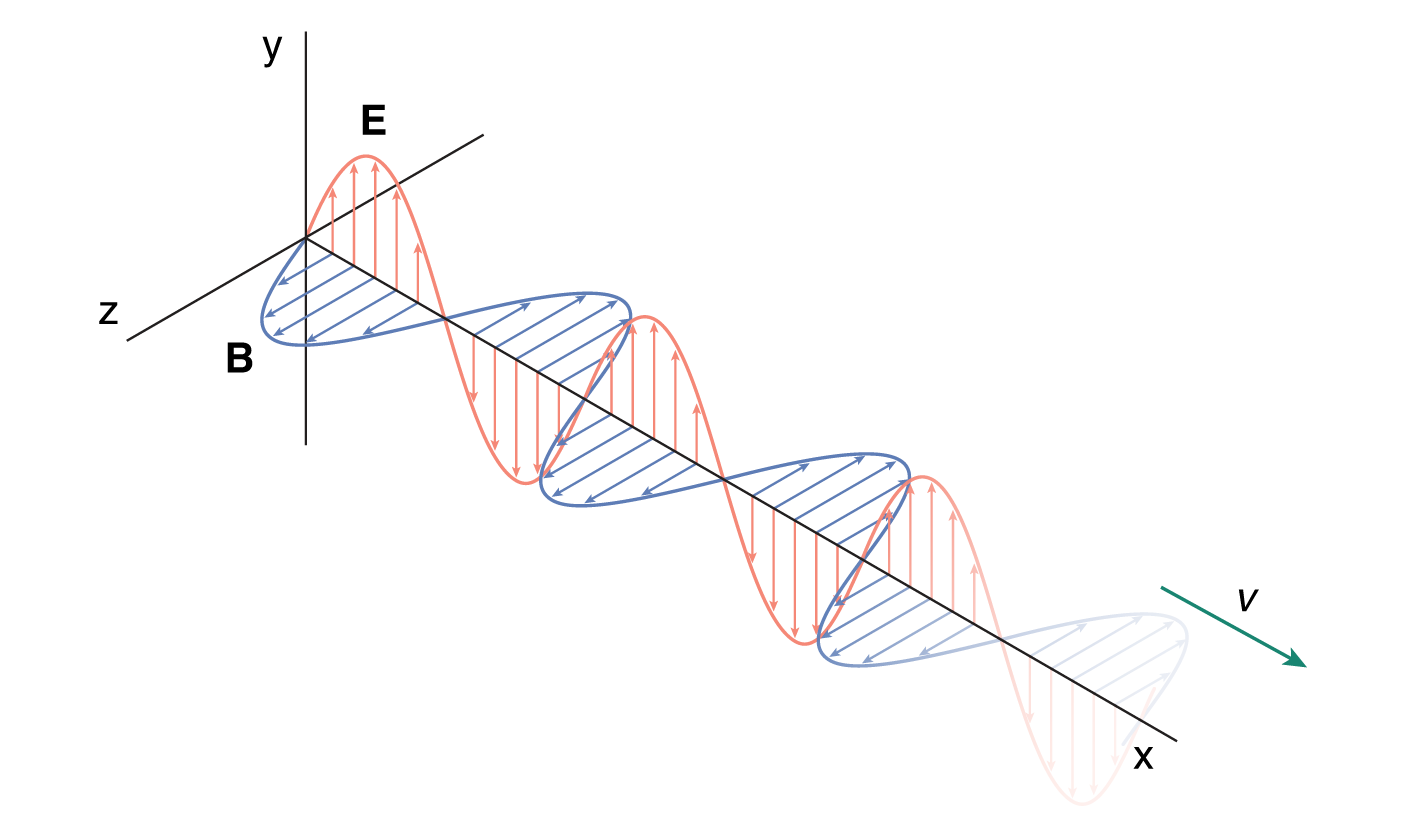
Figure 8.1. Electromagnetic Wave The electric field (E) oscillates up and down the page; the magnetic field (B) oscillates into and out of the page.
The electromagnetic spectrum describes the full range of frequencies and wavelengths of electromagnetic waves. Wavelengths are often given in the following units: mm (10–3 m), µm (10–6 m), nm (10–9 m), and Å (ångström, 10–10 m). The full spectrum is broken up into many regions, which in descending order of wavelength are radio (109–1 m), microwave (1 m–1 mm), infrared (1 mm–700 nm), visible light (700–400 nm), ultraviolet (400–50 nm), X-rays (50–10–2 nm), and γ-rays (less than 10–2 nm). The electromagnetic spectrum is depicted in Figure 8.2.
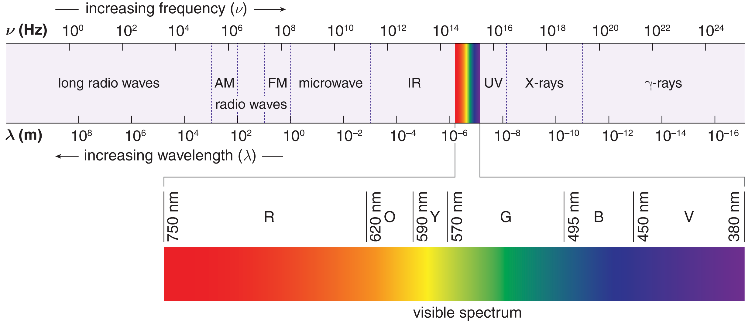
Figure 8.2. The Electromagnetic Spectrum
Electromagnetic waves vary in frequency and wavelength, but in a vacuum, all electromagnetic waves travel at the same speed, called the speed of light. This constant is represented by c and is approximately 3.00×10⁸ ms. To a first approximation—and for the purposes of all MCAT-related equations—electromagnetic waves also travel in air with this speed. In reference to electromagnetic waves, the familiar equation ν = fλ becomes
c = fλ
Equation 8.1
where c is the speed of light in a vacuum and, to a first approximation, also in air, f is the frequency, and λ is the wavelength.
MNEMONIC
To recall the order of the colors in the visible spectrum, remember the grade-school “rainbow” of ROY G. BV (red, orange, yellow, green, blue, violet).
Color and the Visible Spectrum
The only part of the spectrum that is perceived as light by the human eye is the visible region. Within this region, different wavelengths are perceived as different colors, with violet at one end of the visible spectrum (400 nm) and red at the other (700 nm).
MCAT EXPERTISE
Wavelengths in the visible range are common on the MCAT. Remembering the boundaries of the visible spectrum (about 400–700 nm) will save you time and energy on Test Day.
Light that contains all the colors in equal intensity is perceived as white. The color of an object that does not emit its own light is dependent on the color of light that it reflects. Thus, an object that appears red is one that absorbs all colors of light except red. This implies that a red object under green illumination will appear black because it absorbs the green light and has no light to reflect. The term blackbody refers to an ideal absorber of all wavelengths of light, which would appear completely black if it were at a lower temperature than its surroundings.
MCAT CONCEPT CHECK 8.1
Before you move on, assess your understanding of the material with these questions.
- Order the types of electromagnetic radiation from highest energy to lowest energy. What other property of light follows the same trend?
_____> ___> ___> ___> ___> ___> _____
- Also follows the same trend: ______________________
- True or False: Light waves are longitudinal because the direction of propagation is perpendicular to the direction of oscillation.
- What are the boundaries of the visible spectrum? How does the range of the visible spectrum compare to the range of the full electromagnetic spectrum?
_________________________________
8.2 Geometrical Optics
LEARNING OBJECTIVES
After Chapter 8.2, you will be able to:
- Apply the sign conventions for mirrors and lenses to optics systems
- Describe the bending of light as it moves between media with different refractive indices
- Explain the impact of dispersion effects and aberrations on the behavior of light
- Recall Snell’s law and other key optics equations
- Solve optics and Snell’s law problems
When light travels through a homogeneous medium, it travels in a straight line. This is known as rectilinear propagation. The behavior of light at the boundary of a medium or interface between two media is described by the theory of geometrical optics. Geometrical optics explains reflection and refraction, as well as the applications of mirrors and lenses.
Reflection
Reflection is the rebounding of incident light waves at the boundary of a medium. Light waves that are reflected are not absorbed into the second medium; rather, they bounce off of the boundary and travel back through the first medium. Figure 8.3 illustrates reflection on a plane mirror.
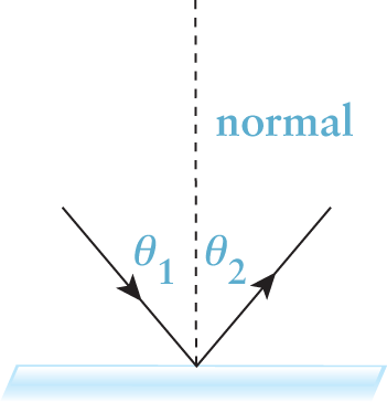
Figure 8.3. Reflection According to the law of reflection, θ1 = θ2.
The law of reflection is
θ1 = θ2
Equation 8.2
where θ1 is the incident angle and θ2 is the reflected angle, both measured from the normal. The normal is a line drawn perpendicular to the boundary of a medium; all angles in optics are measured from the normal, not the surface of the medium.
Plane Mirrors
In general, images created by a mirror can be either real or virtual. An image is said to be real if the light actually converges at the position of the image. An image is virtual if the light only appears to be coming from the position of the image but does not actually converge there. One of the distinguishing features of real images is the ability of the image to be projected onto a screen.
Parallel incident light rays remain parallel after reflection from a plane mirror; that is, plane mirrors—being flat reflective surfaces—cause neither convergence nor divergence of reflected light rays. Because the light does not converge at all, plane mirrors always create virtual images. In a plane mirror, the image appears to be the same distance behind the mirror as the object is in front of it, as shown in Figure 8.4. In other words, plane mirrors create the appearance of light rays originating behind the mirrored surface. Because the reflected light remains in front of the mirror but the image appears behind the mirror, the image is virtual. Plane mirrors include most of the common mirrors found in our homes. To assist in our discussion of spherical mirrors, plane mirrors can be conceptualized as spherical mirrors with an infinite radius of curvature.
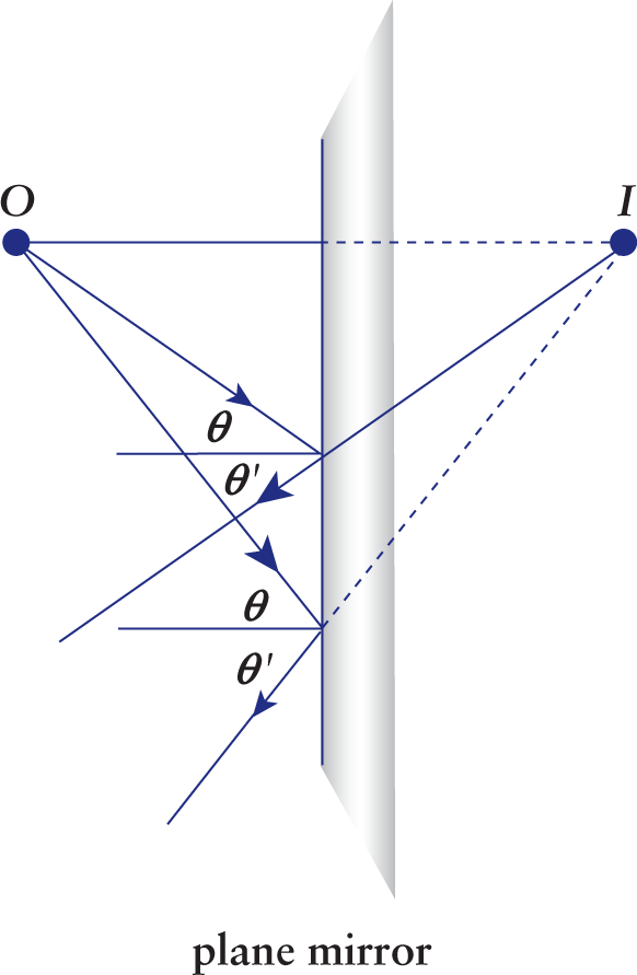
Figure 8.4. Reflection in a Plane Mirror O is the object and I is the (virtual) image; all incident angles (θ) are equal to their respective reflected angles (θ′).
Spherical Mirrors
Spherical mirrors come in two varieties: concave and convex. The word spherical implies that the mirror can be considered a spherical cap or dome taken from a much larger spherically shaped mirror. Spherical mirrors have an associated center of curvature (C) and a radius of curvature (r). The center of curvature is a point on the optical axis located at a distance equal to the radius of curvature from the vertex of the mirror; in other words, the center of curvature would be the center of the spherically shaped mirror if it were a complete sphere.
REAL WORLD
The passenger-side mirrors in cars are an example of convex mirrors (everything appears smaller and farther away); the small circular mirrors used for applying makeup are an example of concave mirrors (everything appears bigger and closer).
If we were to look from the inside of a sphere to its surface, we would see a concave surface. On the other hand, if we were to look from outside the sphere, we would see a convex surface. For a concave surface, the center of curvature and the radius of curvature are located in front of the mirror. For a convex surface, the center of curvature and the radius of curvature are behind the mirror. Concave mirrors are called converging mirrors and convex mirrors are called diverging mirrors because they cause parallel incident light rays to converge and diverge after they reflect, respectively.
MNEMONIC
Concave is like looking into a cave.
KEY CONCEPT
Concave mirrors are converging mirrors. Convex mirrors are diverging mirrors. The reverse is true for lenses.
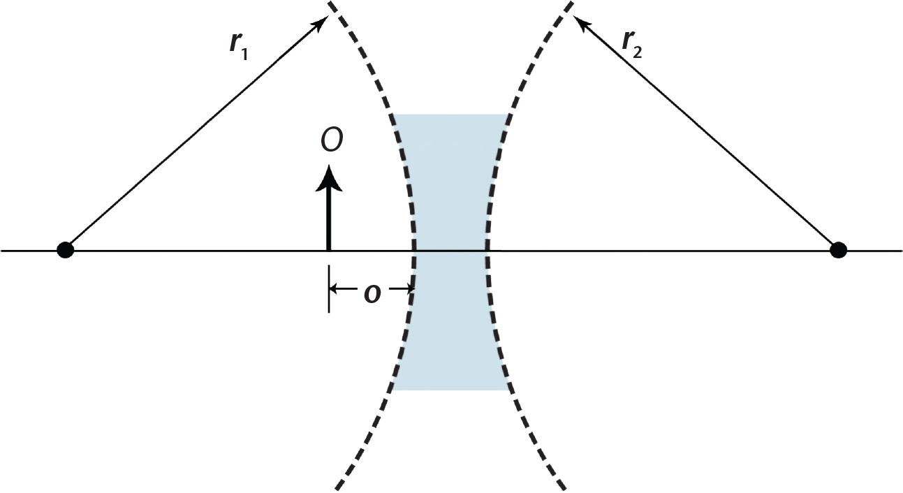
There are several important lengths associated with mirrors, as shown in Figure 8.5. The focal length (f) is the distance between the focal point (F) and the mirror. Note that for all spherical mirrors, f=r2 where the radius of curvature (r) is the distance between C and the mirror. The distance between the object and the mirror is o; the distance between the image and the mirror is i.
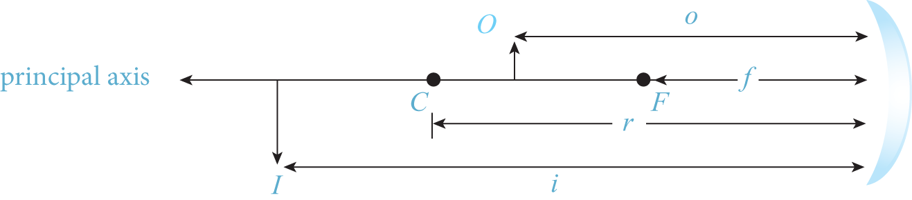
Figure 8.5. Key Variables in Geometrical Optics The mirror pictured is a concave mirror; light rays are not shown.
There is a simple relationship between these four distances:
1f=1o+1i=2r
Equation 8.3
While it is not important which units of distance are used in this equation, it is important that all values used have the same units as each other.
On the MCAT, you will most often use this equation to calculate the image distance for all types of mirrors and lenses. If the image has a positive distance (i > 0), it is a real image, which implies that the image is in front of the mirror. If the image has a negative distance (i < 0), it is virtual and thus located behind the mirror. Plane mirrors can be thought of as spherical mirrors with infinitely large focal distances. As such, for a plane mirror, r = f = ∞, and the equation becomes 1o+1i=0 or i = –o. This can be interpreted as saying the virtual image is at a distance behind the mirror equal to the distance the object is in front of the mirror.
The magnification (m) is a dimensionless value that is the ratio of the image distance to the object distance:
m=−io
Equation 8.4
By extension, the magnification also gives the ratio of the size of the image to the size of the object. Following the sign convention given later in Table 8.1, the orientation of the image (upright or inverted) can be determined: a negative magnification signifies an inverted image, while a positive value signifies an upright image. If |m| < 1, the image is smaller than the object (reduced); if |m| > 1, the image is larger than the object (enlarged); and if |m| = 1, the image is the same size as the object.
Figure 8.6 shows ray diagrams for a concave spherical mirror with the object at three different points. A ray diagram is useful for getting an approximation of where an image is. On Test Day, ray diagrams can be helpful for a quick determination of the type of image that will be produced by an object some distance from the mirror (real vs. virtual, inverted vs. upright, and magnified vs. reduced). Ray diagrams should be used with caution, however: under the pressure of Test Day, it can be easy to draw them incorrectly. Therefore, it is important to practice drawing ray diagrams to avoid careless errors on Test Day, and it is also important to be familiar with how to solve optics questions mathematically.
When drawing a ray diagram, there are three important rays to draw. For a concave mirror, a ray that strikes the mirror parallel to the axis (the normal passing through the center of the mirror) is reflected back through the focal point (green lines in Figure 8.6 and 8.7). A ray that passes through the focal point before reaching the mirror is reflected back parallel to the axis (red lines). A ray that strikes the mirror at the point of intersection with the axis is reflected back with the same angle measured from the normal (blue lines). In Figure 8.6a, the object is placed beyond F, and the image produced is real, inverted and magnified. In Figure 8.6b, the object is placed at F, and no image is formed because the reflected light rays are parallel to each other. In terms of the mirror equation, we say that the image distance i = ∞ here. For the scenario in Figure 8.6c, the object is placed between F and the mirror, and the image produced is virtual, upright, and magnified.
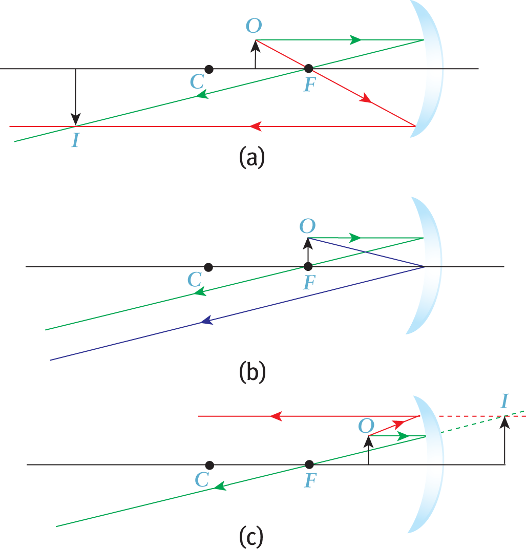
Figure 8.6. Ray Diagrams for Concave (Converging) Mirrors (a) Object is placed beyond F; (b) Object is placed at F; (c) Object is placed between F and the mirror.
KEY CONCEPT
Any time an object is at the focal point of a converging mirror, the reflected rays will be parallel, and thus, the image will be at infinity.
A single diverging mirror forms only a virtual, upright, and reduced image, regardless of the position of the object. The farther away the object, the smaller the image will be. To quickly remember these rules, recall the convenience store security mirrors mentioned at the beginning of the chapter. The ray diagram of a diverging mirror is shown in Figure 8.7.
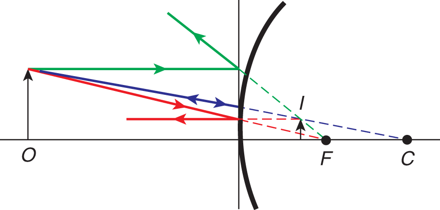
Figure 8.7. Ray Diagrams for Convex (Diverging) Mirrors
KEY CONCEPT
To find where the image is (for a mirror), draw the following rays and find a point where any two intersect. This point of intersection marks the tip of the image. If the rays you draw do not appear to intersect, extend them to the other side of the mirror, creating a virtual image.
- Ray parallel to axis → reflects back through focal point
- Ray through focal point → reflects back parallel to axis
- Ray to center of mirror → reflects back at same angle relative to normal
Sign Conventions for Mirrors
Table 8.1 provides the sign convention for single mirrors. Note that on the MCAT, for almost all problems involving mirrors, the object will be placed in front of the mirror. Thus, the object distance o is almost always positive.
Table 8.1 Sign Convention for a Single Mirror
SYMBOL POSITIVE NEGATIVE
o Object is in front of mirror Object is behind mirror (extremely rare)
i Image is in front of mirror (real) Image is behind mirror (virtual)
r Mirror is concave (converging) Mirror is convex (diverging)
f Mirror is concave (converging) Mirror is convex (diverging)
m Image is upright (erect) Image is inverted
KEY CONCEPT
The focal length of converging mirrors (and converging lenses) will always be positive. The focal length of diverging mirrors (and diverging lenses) will always be negative.
MNEMONIC
Image types with a single lens or mirror (assuming o is positive): UV NO IR
- Upright images are always virtual
- No image is formed when the object is a focal length away
- Inverted images are always real
Example: An object is placed 6 cm in front of a concave mirror that has a 10 cm radius of curvature. Determine the image distance, the magnification, whether the image is real or virtual, and whether it is inverted or upright.
Solution: Use the optics equation:
1f=1o+1i=2r1i=2r−1o1i=210 cm−16 cm=12−1060=260i=602=+30 cm
A positive value for i signifies that the image is in front of the mirror and is therefore real. For a single lens or mirror with o > 0, a real image will always be inverted.
After determining i, the magnification m can be calculated as:
m=−io=−30 cm6 cm=−5
The negative sign on the magnification confirms that the image is inverted, and the fact that |m| > 1 indicates that the image is enlarged.
Refraction
Refraction is the bending of light as it passes from one medium to another and changes speed. The speed of light through any medium is always less than its speed through a vacuum. Remember that the speed of light in a vacuum, c, is equal to 3.00×10⁸ ms. The speed of light in air is just slightly lower that this value; on the MCAT, it is appropriate to use 3.00×10⁸ ms for the speed of light in air.
REAL WORLD
When a pencil (or any straight object) is dipped into a glass of water at an angle, it looks impossibly bent where it intersects the surface of the water because the light reflecting off of the portion of the pencil under water is refracted.
Snell’s Law
When light is in any medium besides a vacuum, its speed is less than c. For a given medium
n=cv
Equation 8.5
where c is the speed of light in a vacuum, ν is the speed of light in the medium, and n is a dimensionless quantity called the index of refraction of the medium. The index of refraction of a vacuum is 1, by definition; for all other materials, the index of refraction will be greater than 1. For air, n is essentially equal to 1 because the speed of light in air is extremely close to c. The indices of refraction for a number of common media are shown in Table 8.2. These values are provided only for reference; they need not be memorized.
Table 8.2 Indices of Refraction of Common Media
MEDIUM INDEX OF REFRACTION (n)
Vacuum 1 (by definition)
Air 1.0003
Ice 1.31
Water 1.33
Acetone 1.36
Ethanol 1.36
Cornea (human) 1.37–1.40
Lens (human) 1.39–1.41
Glass (various types) 1.48–1.93
Diamond 2.42
Refracted rays of light obey Snell’s law as they pass from one medium to another:
n1 sin θ1 = n2 sin θ2
Equation 8.6
where n1 and θ1 refer to the medium from which the light is coming and n2 and θ2 refer to the medium into which the light is entering. Note that θ is once again measured with respect to the normal, as shown in Figure 8.8.
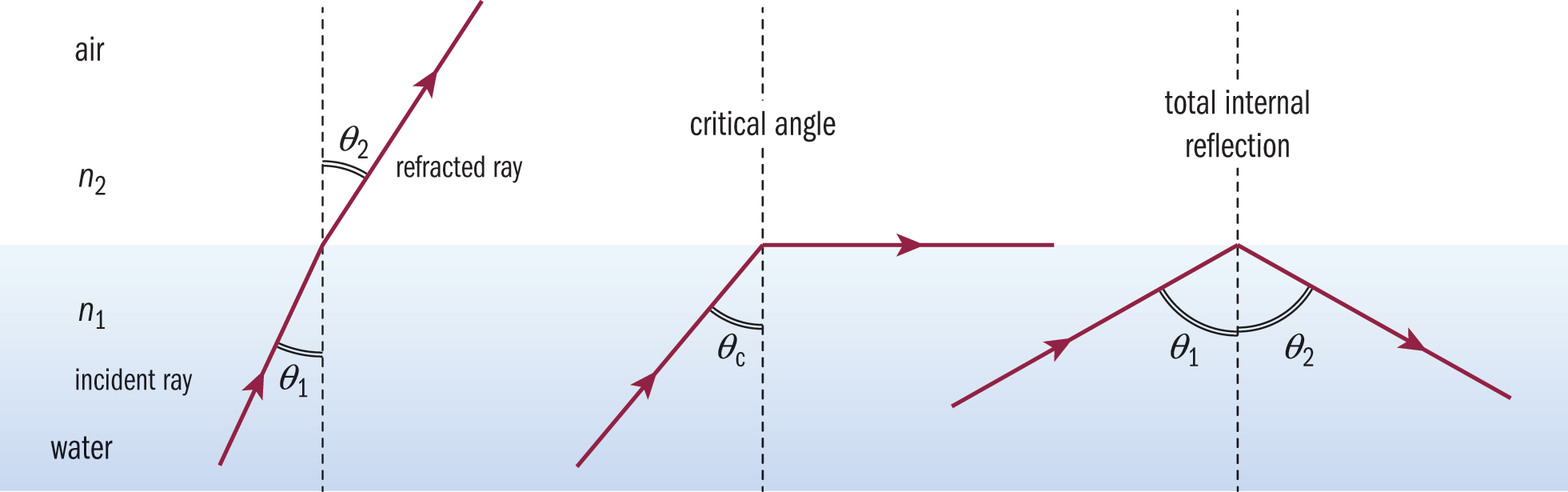
Figure 8.8. Snell’s Law
From Snell’s law, we can see that when light enters a medium with a higher index of refraction (n2 > n1), it bends toward the normal (sin θ2 < sin θ1; therefore, θ2 < θ1), as shown in Figure 8.9. Conversely, if the light travels into a medium where the index of refraction is smaller (n2 < n1), the light will bend away from the normal (sin θ2 > sin θ1; therefore, θ2 > θ1).
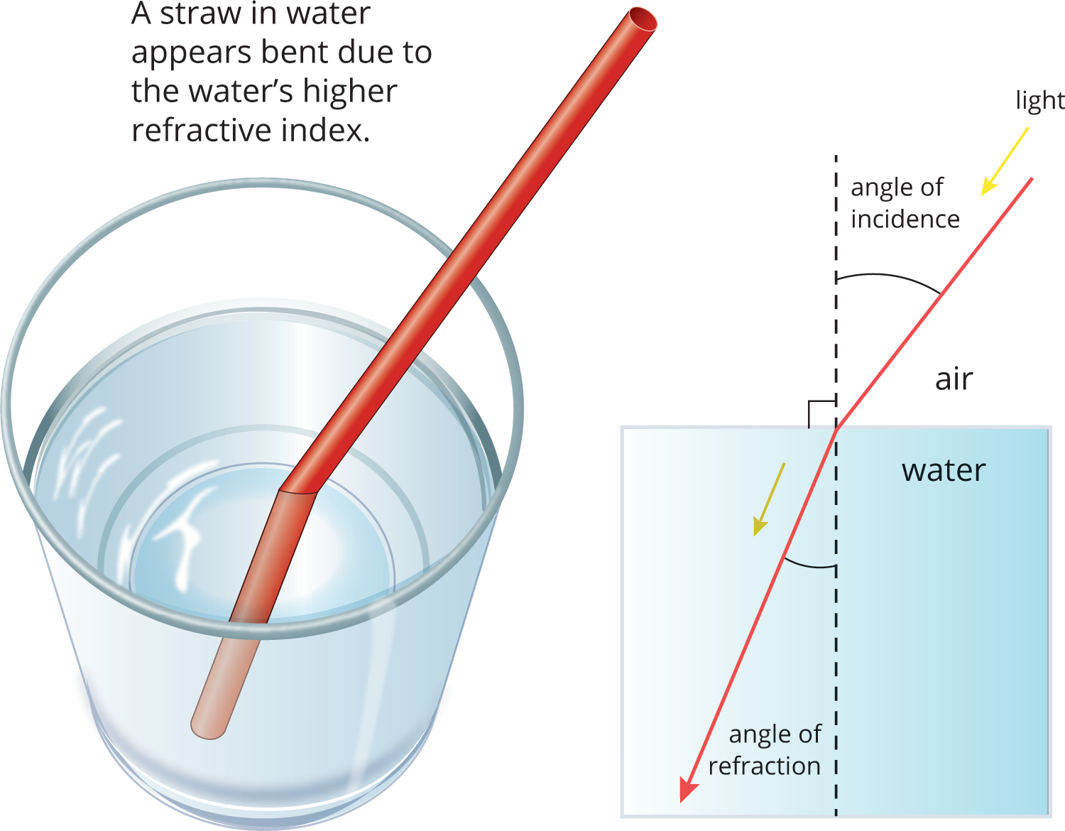
Figure 8.9 Refraction of Light from Air into Water
KEY CONCEPT
Remember that when light enters a medium with a higher index of refraction, it bends toward the normal. When light enters a medium with a lower index of refraction, it bends away from the normal.
Example: A penny sits at the bottom of a pool of water (n = 1.33) at a depth of 3.0 m. If an observer 1.8 m tall stands 30 cm away from the edge, how close to the side can the penny be and still be visible?
Solution: First, draw a picture of the situation:
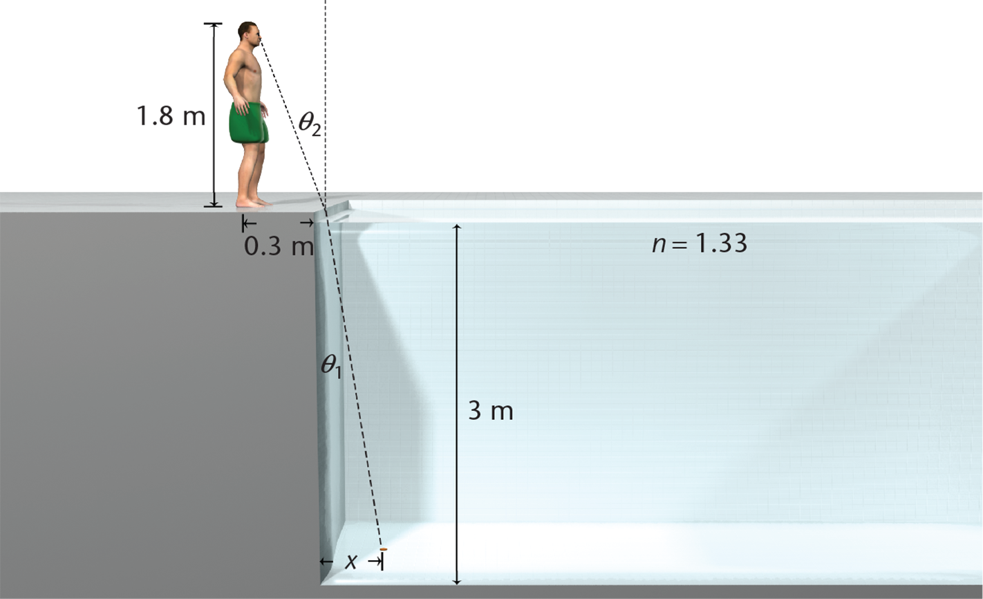
Note that the light is coming from the water (n1 = 1.33) and going into the air (n2 ≈ 1), so the light is bent away from the normal (θ2 > θ1). We need to find the angle that the light rays make with the normal to the water’s surface:
tan θ2=0.3 m1.8 m=0.167θ2=tan−10.167=9.5°
Using Snell’s law, we can solve for θ1:
sinθ1=(n2n1)sinθ2=(11.33)sin9.5°=0.1651.33θ1=sin−1(0.1651.33)=7.1°
Now, we can find x using trigonometry:
x = (3 m) × tan θ1 = 3 tan 7.1° = 3 × 0.124 = 0.37 m = 37 cm
Note that you will not be expected to calculate precise values of trigonometric functions or inverse trigonometric functions on Test Day. This question is provided mainly as an opportunity to see the application of Snell’s law.
Total Internal Reflection
When light travels from a medium with a higher index of refraction (such as water) to a medium with a lower index of refraction (such as air), the refracted angle is larger than the incident angle (θ2 > θ1); that is, the refracted light ray bends away from the normal. As the incident angle is increased, the refracted angle also increases, and eventually, a special incident angle called the critical angle (θc) is reached, for which the refracted angle θ2 equals 90 degrees. At the critical angle, the refracted light ray passes along the interface between the two media. The critical angle can be derived from Snell’s law if θ2 = 90°, such that
θc=sin−1(n2n1)
Equation 8.7 Total internal reflection, a phenomenon in which all the light incident on a boundary is reflected back into the original material, results with any angle of incidence greater than the critical angle, θc, as shown in Figure 8.10.
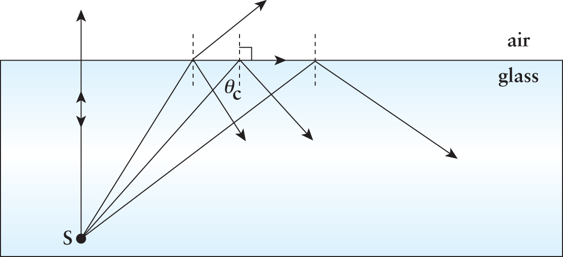
Figure 8.10. Total Internal Reflection At the incident angle ofθc, the refracted angle is equal to 90°; at incident angles above 90°, total internal reflection occurs.
KEY CONCEPT
Total internal reflection occurs as the light moves from a medium with a higher refractive index to a medium with a lower one.
Example: From the previous example, suppose another penny is 3 m away from the edge. Will a light ray going from this penny to the edge of the pool emerge from the water?
Solution: The angle made by the second penny’s light ray is
θ1=tan−1(oppositeadjacent)=tan−1(3 m3 m)=tan−1(1)=45°
Find the critical angle:
θc=sin−1(n2n1)=sin−1(11.33)=sin−1(0.75)=48.8°
It is not expected on the MCAT that we know the inverse sin of 0.75. However, we do know that sin45°=22≈0.71. Since sin (θc) is greater than 0.71, the critical angle must be greater than 45°. Therefore, θc > θ1 and the light ray will emerge from the pool.
Lenses
There is an important difference between lenses and mirrors, aside from the fact that lenses refract light while mirrors reflect it. When working with lenses, there are two surfaces that affect the light path. For example, a person wearing glasses sees light that travels from an object through the air into the glass lens (first surface). Then the light travels through the glass until it reaches the other side, where again it travels out of the glass and into the air (second surface). The light is refracted twice as it passes from air to lens and from lens back to air.
Thin Spherical Lenses
On the MCAT, lenses generally have negligible thickness. Because light can travel from either side of a lens, a lens has two focal points, with one on each side. The focal length can be measured in either direction from the center. For thin spherical lenses, the focal lengths are equal, so we speak of just one focal length for the lens as a whole.
Figure 8.11a illustrates that a converging lens is always thicker at the center, while Figure 8.11b illustrates that a diverging lens is always thinner at the center. The basic formulas for finding image distance and magnification for spherical mirrors also apply to lenses. The object distance o, image distance i, focal length f, and magnification m, are related by the equations 1f=1o+1i and m=−io.
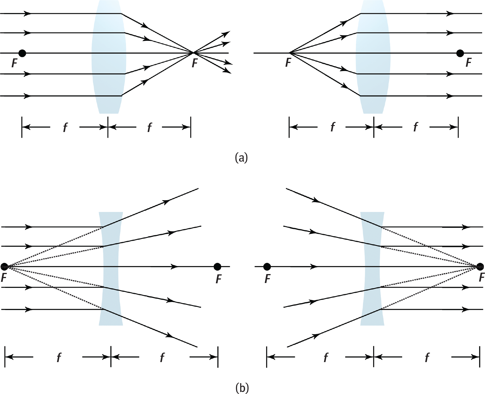
Figure 8.11. Ray Diagrams for Single Lenses (a) Convex (converging) lenses; (b) Concave (diverging) lenses.
REAL WORLD
Converging lenses (reading glasses) are needed by people who are “farsighted.” Diverging lenses (standard glasses) are needed by people who are “nearsighted.”
Real Lenses
For lenses where the thickness cannot be neglected, the focal length is related to the curvature of the lens surfaces and the index of refraction of the lens by the lensmaker’s equation:
1f=(n−1)(1r1−1r2)
Equation 8.8
where n is the index of refraction of the lens material, r1 is the radius of curvature of the first lens surface, and r2 is the radius of curvature of the second lens surface.
The eye is a complex refractive instrument that uses real lenses. The cornea acts as the primary source of refractive power because the change in refractive index from air is so significant. Then, light is passed through an adaptive lens that can change its focal length before reaching the vitreous humor. It is further diffused through layers of retinal tissue to reach the rods and cones. At this point, the image has been focused and minimized significantly, but is still relatively blurry. Our nervous system processes the remaining errors to provide a crisp view of the world.
KEY CONCEPT
To find where the image is (for a lens), draw the following rays and find a point where any two intersect. This point of intersection marks the tip of the image. If the rays you draw do not appear to intersect, extend them to the same side of the lens from which the light came, creating a virtual image.
- Ray parallel to axis → refracts through focal point of front face of the lens
- Ray through or toward focal point before reaching lens → refracts parallel to axis
- Ray to center of lens → continues straight through with no refraction
Sign Conventions for Lenses
Note that the sign conventions change slightly for lenses. For both lenses and mirrors, positive magnification represents upright images, and negative magnification means inverted images. Also, for both lenses and mirrors, a positive image distance means that the image is real and is located on the real (R) side, whereas a negative image distance means that the image is virtual and located on the virtual (V) side. Table 8.3 summarizes the sign conventions for single lenses.
Table 8.3 Sign Convention for a Single Lens
SYMBOL POSITIVE NEGATIVE
o Object is on same side of lens as light source Object is on opposite side of lens from light source (extremely rare)
i Image is on opposite side of lens from light source (real) Image is on same side of lens as light source (virtual)
r Lens is convex (converging) Lens is concave (diverging)
f Lens is convex (converging) Lens is concave (diverging)
m Image is upright (erect) Image is inverted
KEY CONCEPT
It is important to realize that concave mirrors and convex lenses are both converging and thus have similar properties. Convex mirrors and concave lenses are both diverging and also have similar properties.
The designations of real and virtual are often a point of confusion for students because they are on opposite sides when comparing mirrors and lenses. To identify the real side (R), remember that the real side is where light actually goes after interacting with the lens or mirror. For mirrors, light is reflected and, therefore, stays in front of the mirror. Hence, for a mirror, the real side is in front of the mirror, and the virtual side is behind the mirror. For lenses, the convention is different: because light travels through the lens and comes out on the other side, the real side is on the opposite side of the lens from the original light source, and the virtual side is on the same side of the lens as the original light source. Although the object of a single lens is on the virtual side, this does not make the object virtual. Objects are real, with a positive object distance, unless they are placed in certain multiple lens systems in which the image of one lens becomes the object for another (a scenario which is very rarely encountered on the MCAT).
Focal lengths and radii of curvature have a simpler sign convention. For both mirrors and lenses, converging species have positive focal lengths and radii of curvature, and diverging species have negative focal lengths and radii of curvature. Remember that lenses have two focal lengths and two radii of curvature because they have two surfaces. For a thin lens where thickness is negligible, the sign of the focal length and radius of curvature are given based on the first surface the light passes through.
Power
Optometrists often describe a lens in terms of its **power (P). This is measured indiopters**, where f (the focal length) is in meters and is given by the equation
P=1f
Equation 8.9
P has the same sign as f and is, therefore, positive for a converging lens and negative for a diverging lens. People who are nearsighted (can see near objects clearly) need diverging lenses, while people who are farsighted (can see distant objects clearly) need converging lenses. Bifocal lenses are corrective lenses that have two distinct regions—one that causes convergence of light to correct for farsightedness (hyperopia) and a second that causes divergence of light to correct for nearsightedness (myopia) in the same lens.
MCAT EXPERTISE
The MCAT does expect students to understand what myopia and hyperopia are, as well as their corresponding ray diagrams and correction strategies.
Multiple Lens Systems
Lenses in contact are a series of lenses with negligible distances between them. These systems behave as a single lens with equivalent focal length given by
1f=1f1+1f2+1f3+⋅⋅⋅+1fn
Equation 8.10
Because power is the reciprocal of focal length, the equivalent power is
P = P1 + P2 + P3 + ··· + *P**n*
Equation 8.11
REAL WORLD
The human eye typically has an optical power of around 60 diopters. Most contact lens wearers have prescriptions between 0.25 and 8 diopters (both positive and negative). An eye that requires a +8 or −8 prescription still has an optical power that is about 87% of the typical value.
A good example of lenses in contact is a corrective contact lens worn directly on the eye. In this case, the cornea of the eye (a converging lens) is in contact with a contact lens (either converging or diverging, depending on the necessary correction), and their powers would be added.
For lenses not in contact, the image of one lens becomes the object of another lens. The image from the last lens is considered the image of the system. Microscopes and telescopes are good examples of these systems. The magnification for the system is
m = m1 × m2 × m3 × ··· × mn
Equation 8.12
MCAT EXPERTISE
Because the MCAT is a timed test, you will not be given a massive multiple lens system and be expected to make calculations, although the testmaker might test a multiple-lens system conceptually.
Example: An object is 15 cm to the left of a thin diverging lens with a 45 cm focal length as shown below. Find where the image is formed, if it is upright or inverted, and if it is real or virtual. What is the radius of curvature, assuming the lens is symmetrical and is made of glass with a non negligible thickness and an index of refraction of 1.50?
Solution: The image distance (i) is found using the equation
1f=1o+1i→1i=1f−1o
Because the lens is diverging, the focal length has a negative sign (f = −45 cm). The object, like any object in a single-lens system, has a positive sign (o = +15 cm). Now we can solve for i:
1i=1f−1o=1−45 cm−115 cm=−1−345=−445i=−454=−11.25 cm
The negative sign indicates that the image is on the same side of the light source and is virtual. Remember that for a single lens or mirror, virtual images are always upright.
The thickness of a lens is usually negligible, but we are told otherwise in this question. To determine the radii of curvature, we use the lensmaker’s equation. Because the lens is symmetrical, the radii are equal but opposite in sign. As the light progresses from left to right, the first surface of the lens is concave (r1 < 0), and the second surface of the lens is convex (r2 > 0).
1f=(n−1)(1r1−1r2)=(n−1)(−1r−1r)=(n−1)(−2r)r=−2f(n−1)=−2(−45 cm)(1.5−1)=2(45)(0.5)=45 cm
Spherical Aberration
Spherical mirrors and lenses are imperfect. They are therefore subject to specific types of errors or aberrations. Spherical aberration is a blurring of the periphery of an image as a result of inadequate reflection of parallel beams at the edge of a mirror or inadequate refraction of parallel beams at the edge of a lens. This creates an area of multiple images with very slightly different image distances at the edge of the image, which appears blurry. This phenomenon can be seen in Figure 8.12.
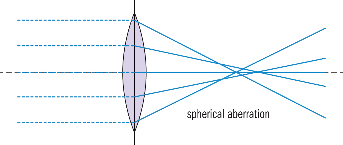
Figure 8.12. Spherical Aberration Parallel rays are not perfectly reflected or refracted through the focal point, leading to blurriness at the periphery of the image.
REAL WORLD
If you remember back to conic sections from your precalculus class, it should be no surprise that spherical mirrors and lenses do not focus light perfectly. Parabolas are perfect reflectors, meaning that parallel light rays are reflected perfectly through the focal point. This is used in extracorporeal shock wave lithotripsy, in which a parabolic mirror is positioned with a kidney stone at the focal point. Sound waves are reflected off of the mirror and create enough vibration in the kidney stone to shatter it.
Chromatic aberration, discussed below, is predominantly seen in spherical lenses.
Dispersion
As discussed earlier, the speed of light in a vacuum is the same for all wavelengths. However, when light travels through a medium, different wavelengths travel at different speeds. This fact implies that the index of refraction of a medium affects the wavelength of light passing through the medium because the index of refraction is related to the speed of the wave by n=cv. It also implies that the index of refraction itself actually varies with wavelength. When various wavelengths of light separate from each other, this is called dispersion. The most common example of dispersion is the splitting of white light into its component colors using a prism.
If a source of white light is incident on one of the faces of a prism, the light emerging from the prism is spread out into a fan-shaped beam, as shown in Figure 8.13. This occurs because violet light has a smaller wavelength than red light and so is bent to a greater extent. Because red experiences the least amount of refraction, it is always on top of the spectrum; violet, having experienced the greatest amount of refraction, is always on the bottom of the spectrum. Note that as light enters a medium with a different index of refraction, the wavelength changes but the frequency of the light does not.
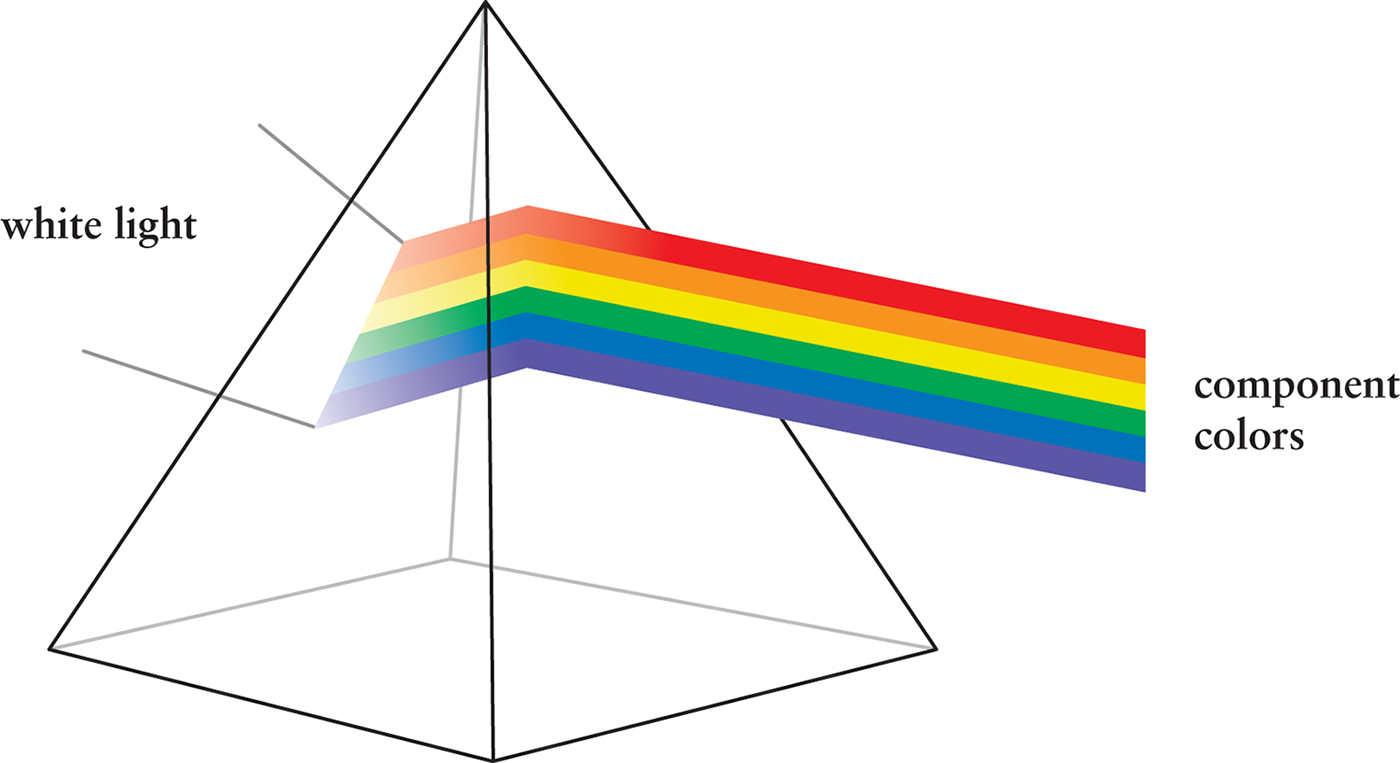
Figure 8.13. Dispersion in a Prism Due to their different speeds while inside the prism, the various wavelengths of light are refracted to different degrees.
Chromatic Aberration
Chromatic aberration, shown in Figure 8.14, is a dispersive effect within a spherical lens. Depending on the thickness and curvature of the lens, there may be significant splitting of white light, which results in a rainbow halo around images. This phenomenon is corrected for in visual lenses like eyeglasses and car windows with special coatings that have different dispersive qualities from the lens itself.
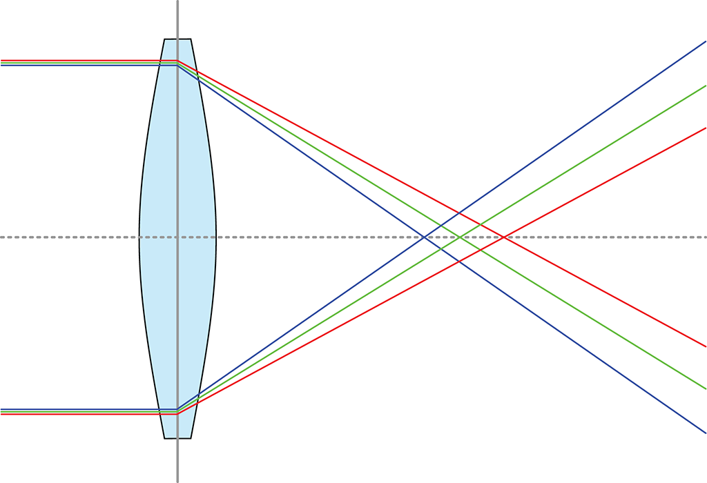
Figure 8.14. Chromatic Aberration Light dispersion within the glass lens leads to the formation of a rainbow halo at the edge of the image.
MCAT CONCEPT CHECK 8.2
Before you move on, assess your understanding of the material with these questions.
- Populate the following tables according to the sign conventions for mirrors and lenses:
**Mirrors Symbol Positive Negative o i r f m Lenses Symbol Positive Negative *o i r f m***
- True or False: Incident angle is always measured with respect to the normal.
- Describe the bending of light when moving from a medium with low refractive index to high refractive index, and from a medium with high refractive index to low refractive index:
- Low n to high n:
_________________________________
- High n to low n:
_________________________________
- Define the following terms:
- Dispersion:
_________________________________
- Aberration:
_________________________________
- What are the two mathematical relationships between image distance and object distance?
_________________________________
8.3 Diffraction
LEARNING OBJECTIVES
After Chapter 8.3, you will be able to:
- Distinguish between the diffraction patterns in single-slit, double-slit, and slit–lens systems
- Recall the wave phenomena that lead to diffraction fringes
- Describe Young’s double-slit experiment:
Diffraction refers to the spreading out of light as it passes through a narrow opening or around an obstacle. Interference between diffracted light rays lead to characteristic fringes in slit–lens and double-slit systems. Diffraction and interference are significant evidence for the wave theory of light.
Single Slit
Although it is usually safe to assume that nonrefracted light travels in a straight line, there are situations where light will not actually travel in a straight-line path. When light passes through a narrow opening (an opening with a size that is on the order of light wavelengths), the light waves seem to spread out (diffract), as is shown in Figure 8.15. As the slit is narrowed, the light spreads out more.
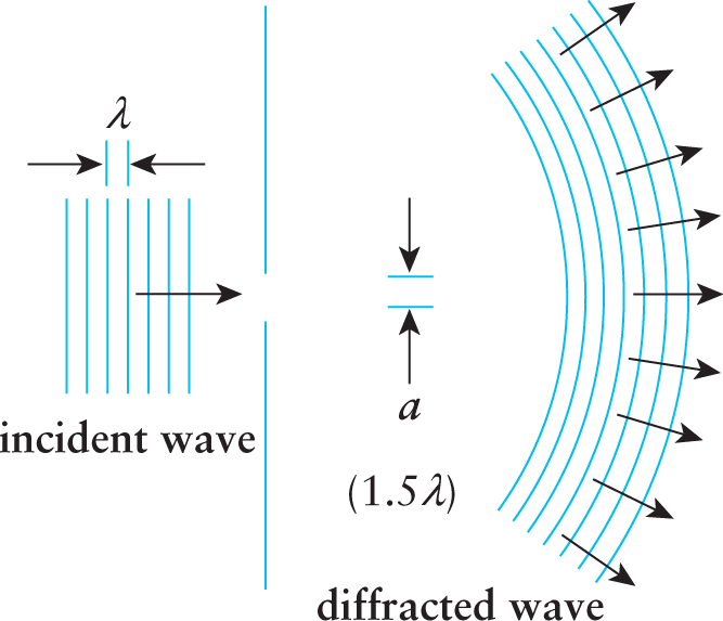
Figure 8.15. Diffraction Light emerges from a narrow slit in a wide arc, not a narrow beam.
Slit–Lens System
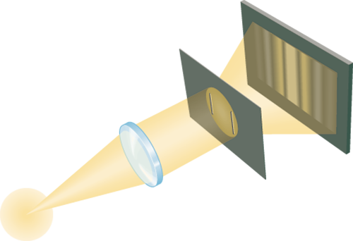
If a lens is placed between a narrow slit and a screen, a pattern is observed consisting of a bright central fringe with alternating dark and bright fringes on each side, as shown in Figure 8.16. The central bright fringe (maximum) is twice as wide as the bright fringes on the sides, and as the slit becomes narrower, the central maximum becomes wider. The location of the dark fringes (minima) is given by the formula
a sin θ = nλ
Equation 8.13
where a is the width of the slit, θ is the angle between the line drawn from the center of the lens to the dark fringe and the axis of the lens, n is an integer indicating the number of the fringe, and λ is the wavelength of the incident wave. Note that bright fringes are halfway between dark fringes.
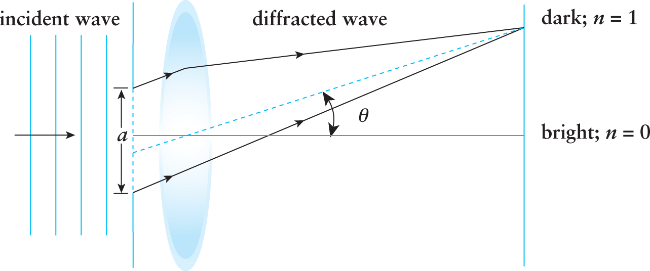
Figure 8.16. Single-Slit Diffraction with Lens
Multiple Slits
When waves interact with each other, the displacements of the waves add together in a process called interference, as described in Chapter 7 of MCAT Physics and Math Review. In his famous double-slit experiment, Thomas Young showed that the diffracted rays of light emerging from two parallel slits can interfere with one another. This was a landmark finding that contributed to the understanding of light as a wave. Figure 8.17 shows the typical setup for Young’s double-slit experiment. When monochromatic light (light of only one wavelength) passes through the slits, an interference pattern is observed on a screen placed behind the slits. Regions of constructive interference between the two light waves appear as bright fringes (maxima) on the screen. Conversely, in regions where the light waves interfere destructively, dark fringes (minima) appear.
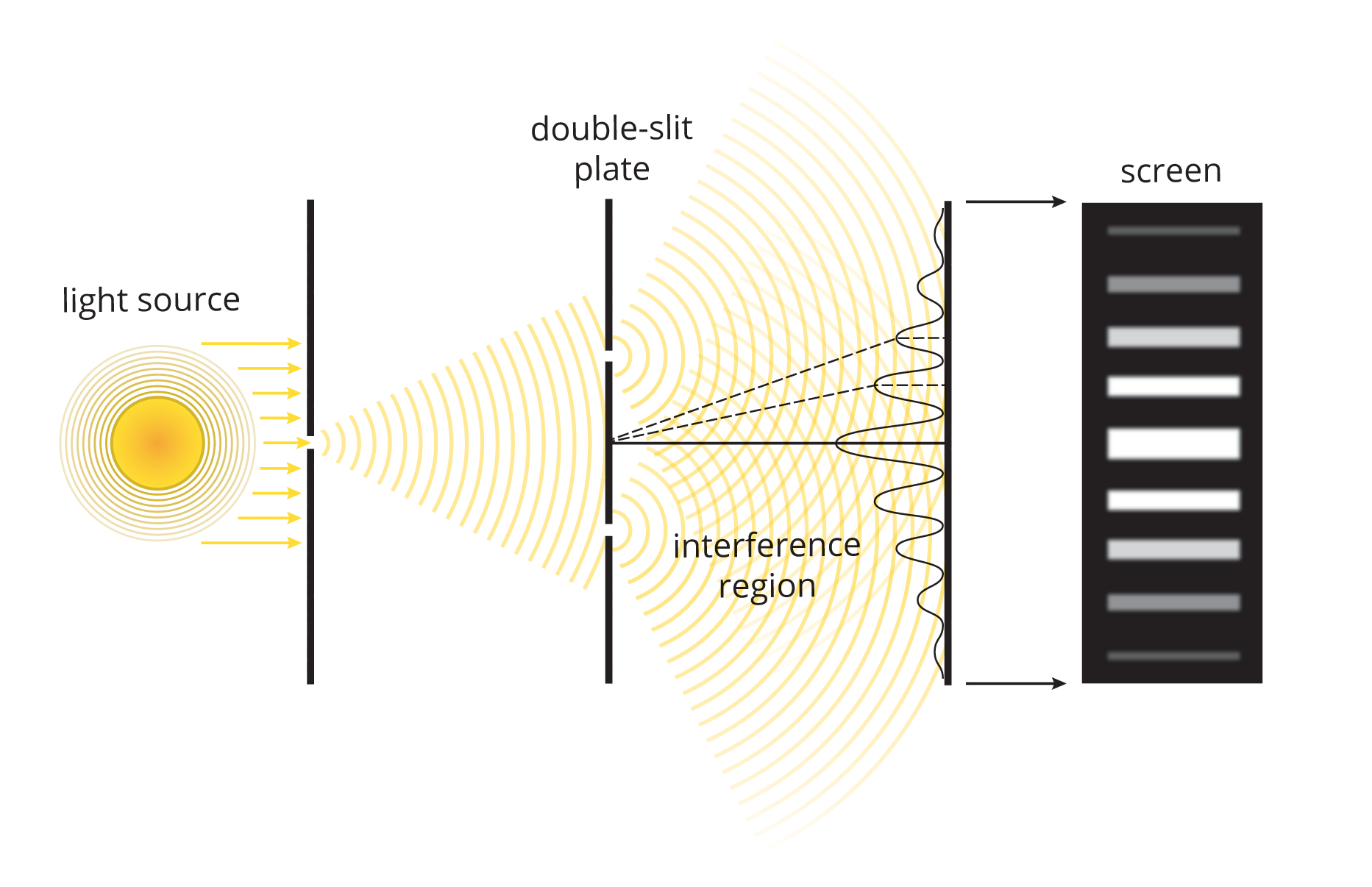
Figure 8.17. Young’s Double-Slit Experiment
BRIDGE
Light is similar to other waveforms; it is affected by constructive and destructive interference when light passes through a slit and a lens, and when light passes through multiple slits. Interference also occurs with sound waves, as discussed in Chapter 7 of MCAT Physics and Math Review.
The positions of dark fringes (minima) on the screen can be found from the equation
dsinθ=(n+12)λ
Equation 8.14
where d is the distance between the two slits, θ is the angle between the line drawn from the midpoint between the two slits to the dark fringe and the normal, n is an integer indicating the number of the fringe, and λ is the wavelength of the incident wave. Note that bright fringes are halfway between dark fringes.
Example: In a double-slit experiment, what is the linear distance y between the sixth and eighth minima on the screen? (Note: The wavelength λ is 550 nm, the slits are separated by a distance of 0.14 mm, and the screen is 70 cm from the slits.)
Solution: The position of a dark fringe (minimum) is given by
dsinθ=(n+12)λ
We do not know the value of sinθ(oppositehypotenuse). However, for small angles, sin θ ≈ tan θ. This is because the length of the hypotenuse is very close to the length of the adjacent side. We do know the value of tanθ(oppositeadjacent), so we can substitute it into the equation and still get very close to the correct answer:
d sin θ=(n+12)λd tan θ≈(n+12)λ d(yD)≈(n+12)λ y≈(n+12)λDdy8−y6≈(n8+12)λDd−(n6+12)λDd Δy≈(Δn)λDd=(2)(550×10−9 m)(0.7 m)0.14×10⁻³ m=550×10−5 m=5.5 mm
Diffraction gratings consist of multiple slits arranged in patterns. Diffraction gratings can create colorful patterns similar to a prism as the different wavelengths interfere in characteristic patterns. For example, the organization of the grooves on a CD or DVD act like a diffraction grating, creating an iridescent rainbow pattern on the surface of the disc. Thin films may also cause interference patterns because light waves reflecting off the external surface of the film interfere with light waves reflecting off the internal surface of the film, as shown in Figure 8.18. Common examples of thin films are soap bubbles or oil puddles in wet parking lots. Note that the interference here is not between diffracted rays, but between reflected rays.
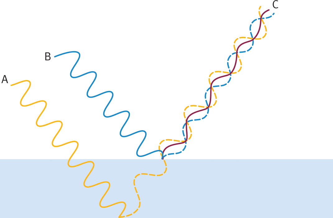
Figure 8.18. Thin Film Interference Interference patterns, C, occur as light waves reflecting off the external surface of the film, B, interfere with light waves reflecting off the internal surface of the film, A. Note that there would be a small degree of refraction as well, although this is not shown in the image.
X-Ray Diffraction
X-ray diffraction uses the bending of light rays to create a model of molecules. X-ray diffraction is often combined with protein crystallography during protein analysis. Dark and light fringes do not take on a linear appearance, but rather a complex two-dimensional image. An example of an x-ray diffraction pattern is shown in Figure 8.19.

Figure 8.19. X-Ray Diffraction Pattern
BRIDGE
X-ray diffraction and protein crystallography are commonly used to analyze the structure of proteins. These techniques, as well as a number of other protein assays, are discussed in Chapter 3 of MCAT Biochemistry Review.
MCAT CONCEPT CHECK 8.3
Before you move on, assess your understanding of the material with these questions.
- How does the diffraction pattern for a single slit differ from a slit with a thin lens?
- Single slit:
_________________________________
- Slit–lens system:
_________________________________
- What wave phenomenon do diffraction fringes result from?
_________________________________
- How does double-slit diffraction and interference differ from single-slit diffraction?
- Double-slit:
_________________________________
- Single-slit:
_________________________________
- True or False: Maxima in diffraction patterns are always equidistant between two minima.
8.4 Polarization
LEARNING OBJECTIVES
After Chapter 8.4, you will be able to:
- Compare and contrast plane-polarized and circularly polarized light
- Describe how a polarized filter impacts the wavelength and/or frequency of light passing through the filter
Plane-Polarized Light
Plane-polarized (or linearly polarized) light is light in which the electric fields of all the waves are oriented in the same direction (that is, their electric field vectors are parallel). It follows that their magnetic field vectors are also parallel, but convention dictates that the plane of the electric field identifies the plane of polarization. Unpolarized light has a random orientation of its electric field vectors; sunlight and light emitted from a light bulb are prime examples. One of the most common applications of plane-polarized light on the MCAT is in the classification of stereoisomers, as discussed in Chapter 2 of MCAT Organic Chemistry Review. The optical activity of a compound, due to the presence of chiral centers, causes plane-polarized light to rotate clockwise or counterclockwise by a given number of degrees relative to its concentration (its specific rotation). Remember that enantiomers, as nonsuperimposable mirror images, will have opposite specific rotations.
REAL WORLD
Plane-polarized light is used to diagnose a number of diseases. Amyloidosis, caused by the buildup of various forms of misfolded proteins, is diagnosed by biopsy and staining the tissue with Congo red stain; a bright “apple green” color is seen under plane-polarized light. Gout (the precipitation of monosodium urate crystals) and pseudogout (the precipitation of calcium pyrophosphate crystals) are differentiated by their precipitate colors under polarized light: monosodium urate appears yellow and calcium pyrophosphate appears blue when the axis of the crystal is aligned with a polarizer.
There are filters called polarizers, often used in cameras and sunglasses, which allow only light with an electric field pointing in a particular direction to pass through. If one passes a beam of light through a polarizer, it will only let through that portion of the light parallel to the axis of the polarizer. If a second polarizer is then held up to the first, the angle between the polarizers’ axes will determine how much light passes through. When the polarizers are aligned, all the light that passes through the first polarizer also passes through the second. When the second polarizer is turned so that its axis is perpendicular, no light gets through at all.
KEY CONCEPT
The electric fields of unpolarized light waves exist in all three dimensions: the direction of the wave’s propagation is surrounded by electric fields in every plane perpendicular to that direction. Polarizing light limits the electric field’s oscillation to only two dimensions.
Circular Polarization
Circular polarization is a rarely seen natural phenomenon that results from the interaction of light with certain pigments or highly specialized filters. Circularly polarized light has a uniform amplitude but a continuously changing direction, which causes a helical orientation in the propagating wave, as shown in Figure 8.20. The helix has average electrical field vectors and magnetic field vectors that lie perpendicular to one another, like other waves, with maxima that fall on the outer border of the helix.
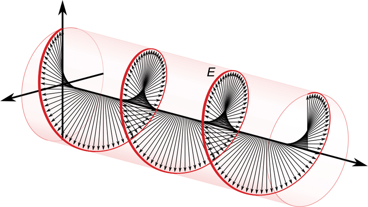
Figure 8.20. Circularly Polarized Light
MCAT CONCEPT CHECK 8.4
Before you move on, assess your understanding of the material with these questions.
- Contrast plane-polarized and circularly polarized light:
- Plane-polarized:
_________________________________
- Circularly polarized:
_________________________________
- How does the application of a polarized filter impact the wavelength of light passing through the filter?
_________________________________
Conclusion
This chapter illuminated the key behaviors and characteristics of light and optical systems. First, we described the nature of the electromagnetic (EM) wave, noting that we can only perceive light in the visible range (400 nm–700 nm). We then focused on geometrical optics to consider the reflective and refractive behaviors of light, noting the ways in which mirrors reflect light to produce images and lenses refract light to produce images. We acknowledged the fact that light doesn’t always travel in straight-line pathways but can bend and spread out through diffraction. We examined the pattern of interference that occurs when light passes through a double slit, as demonstrated in Young’s double-slit experiment. Finally, we wrapped up with a discussion on plane-polarized and circularly polarized light. In this chapter, we considered the properties that support the wave theory of light. In the next chapter, we’ll explore the photon and properties that support the particle theory of light, as well as other atomic and nuclear phenomena.
GO ONLINE
You’ve reviewed the content, now test your knowledge and critical thinking skills by completing a test-like passage set in your online resources!
CONCEPT SUMMARY
Electromagnetic Spectrum
- Electromagnetic waves are transverse waves that consist of an oscillating electric field and an oscillating magnetic field.
- The two fields are perpendicular to each other and to the direction of propagation of the wave.
- The electromagnetic spectrum is the range of frequencies and wavelengths found in EM waves.
- The EM spectrum includes, from lowest to highest energy, radio waves, microwaves, infrared, visible light, ultraviolet, x-rays, and γ-rays.
- The visible spectrum runs from approximately 400 nm (violet) to 700 nm (red).
Geometrical Optics
- Reflection is the rebounding of incident light waves at the boundary of a medium.
- The law of reflection states that the incident angle will equal the angle of reflection, as measured from the normal.
- Spherical mirrors have centers and radii of curvature, as well as focal points.
- Concave mirrors are converging systems and can produce real, inverted images or virtual, upright images, depending on the placement of the object relative to the focal point.
- Convex mirrors are diverging systems and will only produce virtual, upright images.
- Plane mirrors also produce virtual, upright images; these images are always the same size as the object. They may be thought of as spherical mirrors with infinite radii of curvature.
- Refraction is the bending of light as it passes from one medium to another.
- The speed of light changes depending on the index of refraction of the medium. This speed change causes refraction.
- The amount of refraction depends on the wavelength of the light involved; this behavior causes dispersion of light through a prism.
- Snell’s law (the law of refraction) states that there is an inverse relationship between the index of refraction and the sine of the angle of refraction (measured from the normal).
- Total internal reflection occurs when light cannot be refracted out of a medium and is instead reflected back inside the medium.
- This happens when light moves from a medium with a higher index of refraction to a medium with a lower index of refraction with a high incident angle.
- The minimum incident angle at which total internal reflection occurs is called the critical angle.
- Lenses refract light to form images of objects.
- Thin symmetrical lenses have focal points on each side.
- Convex lenses are converging systems and can produce real, inverted images or virtual, upright images.
- Concave lenses are diverging systems and will only produce virtual, upright images.
- Lenses with non negligible thickness require use of the lensmaker’s equation.
- The following table summarizes image creation in converging and diverging systems for both mirrors and lenses:
**Converging Systems Diverging Systems o relative to *f*** o > 2f o = 2f 2f > o > f o = f o < f all object distances
image real, inverted, reduced real, inverted, same real, inverted, magnified no image virtual, upright, magnified
virtual, upright, reduced
Diffraction
- Diffraction is the bending and spreading out of light waves as they pass through a narrow slit.
- Diffraction may produce a large central light fringe surrounded by alternating light and dark fringes with the addition of a lens.
- Interference supports the wave theory of light.
- Young’s double-slit experiment shows the constructive and destructive interference of waves that occur as light passes through parallel slits, resulting in minima (dark fringes) and maxima (bright fringes) of intensity.
Polarization
- In plane-polarized light, all of the light rays have electric fields with parallel orientation.
- Plane-polarized light is created by passing unpolarized light through a polarizer.
- In circularly polarized light, all of the light rays have electric fields with equal intensity but constantly rotating direction.
- Circularly polarized light is created by exposing unpolarized light to special pigments or filters.
ANSWERS TO CONCEPT CHECKS
**8.1**
- γ-rays > x-rays > ultraviolet > visible light > infrared > microwaves > radio. Frequency follows the same trend as energy, whereas wavelength follows the opposite trend.
- False. Light waves are transverse because the direction of propagation is perpendicular to the direction of oscillation.
- Visible light ranges from wavelengths of about 400 nm to 700 nm. This is in comparison to the entire EM spectrum which ranges from wavelengths of nearly 0 to 109 m.
**8.2**
-
**Mirrors Symbol Positive Negative *o*** Object is in front of mirror Object is behind mirror (extremely rare)
i Image is in front of mirror (real) Image is behind mirror (virtual)
r Mirror is concave (converging) Mirror is convex (diverging)
f Mirror is concave (converging) Mirror is convex (diverging)
m Image is upright (erect) Image is inverted
**Lenses Symbol Positive Negative *o*** Object is on same side of lens as light source Object is on opposite side of lens from light source (extremely rare)
i Image is on opposite side of lens from light source (real) Image is on same side of lens as light source (virtual)
r Lens is convex (converging) Lens is concave (diverging)
f Lens is convex (converging) Lens is concave (diverging)
m Image is upright (erect) Image is inverted
- True. In optics, incident angles are always measured relative to the normal.
- Light will bend toward the normal when going from a medium with low n to high n. Light will bend away from the normal when going from a medium with high n to low n; if the incident angle is larger than the critical angle (θc), total internal reflection will occur.
- Dispersion is the tendency for different wavelengths of light to experience different degrees of refraction in a medium, leading to separation of light into the visible spectrum (a rainbow). Aberration (spherical or chromatic) is the alteration or distortion of an image as a result of an imperfection in the optical system.
- 1f=1o+1i and m=−io
**8.3**
- Diffraction through a single slit does not create characteristic fringes when projected on a screen, although the light does spread out. When a lens is introduced into the system, the additional refraction of light causes constructive and destructive interference, creating fringes.
- Fringes result from constructive and destructive interference between light rays.
- The image formed during double-slit diffraction contains fringes because light rays constructively and destructively interfere. A single slit forms an image of a wide band of light, spread out from its original beam.
- True. Maxima and minima alternate in a diffraction pattern. A maximum is equidistant between two minima, and a minimum is equidistant between two maxima.
**8.4**
- Plane-polarized light contains light waves with parallel electric field vectors. Circularly polarized light selects for a given amplitude and has a continuously rotating electric field direction.
- Plane polarization has no effect on the wavelength (or frequency or speed) of light. Polarization does affect the amount of light passing through a medium and light intensity.
SCIENCE MASTERY ASSESSMENT EXPLANATIONS
1. C
It is unnecessary to memorize the entire electromagnetic spectrum for Test Day; however, it is important to know that the visible spectrum runs from 400–700 nm. We can calculate the wavelength of this light ray:
c=fλλ=cf=3×10⁸ms5×1014 Hz=6×10⁻⁷ m=600 nm
This wavelength falls within the visible spectrum and has a yellow-orange color.
2. D
The color of an object is determined by the wavelength of light reflected by that object. Since anthocyanin pigment appears red, it must reflect red light. The frequency of light can be calculated using the equation c = fλ. Red light has a wavelength of 700 nm, which can be converted to 700 × 10-9 m. Plugging in values yields: f = (3 × 10⁸) / (700 × 10-9) = 4.2 × 10¹³ Hz, matching (D). Note that a close eye for units would enable the immediate elimination of (A).
3. A
One could solve this question with a ray diagram, but be wary about using ray diagrams on Test Day. It is easy to make small mistakes that cause the light rays not to intersect. Therefore, solve the question using the sign convention. If the object is at the center of curvature, its distance is 2f. We can plug into the optics equation:
1f=1o+1i→1i=1f−1o=1f−12f=12f i=2f=r
Because i is positive, the image is real. For single mirrors or lenses, all real images are inverted.
4. B
To calculate the wavelength, use the formula: d sin(θ) = (n + 1/2)λ. Rearrange the formula to solve for wavelength: λ = d sin (θ) / (n + 1/2). Since the distance is given in millimeters, first convert to meters; d = 3 × 10⁻⁴ m. Since the question asks for the second dark fringe, we have n = 2. Plugging in the given values yields: λ = (3 × 10⁻⁴)sin (30o) / (2 + 1/2) = 6 × 10⁻⁵ m, matching choice (B).
5. A
This question contains two parts—we have to determine the frequency and the angle of refraction of the light ray. The first part, however, is straightforward because the frequency of a light ray traveling from one medium to another does not change. Because the frequency must be 5 × 10¹⁴ Hz, we can eliminate (C) and (D). For the angle of refraction, we can either calculate it or determine it using logic. First, the light ray goes from air into crystal; that is, from a low index of refraction to a higher one. According to Snell’s law, the angle of refraction will be smaller than the incident angle (closer to the normal). When the light ray moves from crystal to chromium, it again goes from a lower index of refraction into a higher one, thus making the angle of refraction even smaller, eliminating (B). This question could also be answered by calculation using Snell’s law, but the calculations are time consuming and unnecessary.
6. D
Plane-polarized light is light in which the electric fields of all the waves are oriented in the same direction. Light passing through the first two polarizers will only contain rays with their electric field vectors in the same direction. When it reaches the third polarizer, however, the light will not be able to pass through because all the light rays will be oriented in the direction dictated by the first and second polarizers.
7. C
Plane polarizers only allow one specific orientation of the electric field of light to pass through. When plane polarizers are perpendicular to each other, no light can pass through the second polarizer, which supports (C) as the correct answer. Note that if two polarizers are aligned, all of the light that passes through the first will also pass through the second; there is no "twice as plane polarized," eliminating (B).
8. B
The image produced by a convex lens can be either real or virtual. It is real if the object is placed at a distance greater than the focal point, and virtual if the object is placed at a distance less than the focal point (between the focal point and the lens). Remember that for a single mirror or lens, an image that is real must be inverted and one that is virtual must be upright. In this question, the object is placed in front of the focal point, so the image must be virtual and, therefore, upright. We could also determine this from the optics equation. If f > o, then 1f−1o is negative, and i is therefore negative (virtual).
9. D
This question is testing our understanding of total internal reflection. As the laser beam travels from water to air—that is, from a higher to a lower index of refraction—the angle of refraction increases. At the critical angle (θc), the angle of refraction becomes 90°; at this point, the refracted ray is parallel to the surface of the water. When the incident angle is greater than the critical angle, all the light is reflected back into the water. The question is asking for the critical angle:
θc=sin−1n2n1=sin−111.33=sin−10.75
The inverse sine of 0.75 must be slightly higher than 45°(sin45°=22=0.707). 48.59° is the exact answer.
10. C
This question is testing our understanding of diffraction. When light passes through a narrow opening, the light waves spread out; as the slit narrows, the light waves spread out even more. When a lens is placed between the narrow slit and the screen, a pattern consisting of alternating bright and dark fringes can be observed on the screen. As the slit becomes narrower, the central maximum (the brightest and most central fringe) becomes wider. This can also be seen in the equation for the position of dark fringes in a slit–lens setup (a sin θ = nλ). As a, the width of the slit, decreases, sin θ must increase because nλ is constant for a given fringe. If sin θ increases, θ necessarily increases, implying that the fringes are spreading farther apart.
11. D
All images produced by plane mirrors will be virtual, so statement III is true. The same goes for diverging species (convex mirrors and concave lenses), so statement II is true. Converging species (concave mirrors and convex lenses) can produce real or virtual images, depending on how far the object is from the species, so statement I is also true.
12. A
First, the color of the light is irrelevant here; the ratio would be the same even if the specific color were not mentioned. Second, recall Snell’s Law: n1 sin θ1 = n2 sin θ2. Although we don’t know the value of n for either medium, you do know the simple relationship n=cv. Replacing n in Snell’s law, and canceling out c from both sides, we get:
cv1 sin θ1=cv2 sin θ2 sin30°v1=sin45°v2 12v1=22v2 v2=v12
13. D
The overall magnification of a system of multiple lenses is simply the product of each lens’s magnification. In this case, that is 10 × 40 = 400.
14. D
Drawing a diagram is best here. Because the angle given is with respect to the normal, you know that the incident angle must equal 60°. You know that the reflected beam will have an angle of 60° relative to the normal. Therefore, the reflected beam will make an angle of 30° with the plane of the glass. If the reflected and refracted beams are perpendicular to each other, the refracted beam will make a 60° angle with the plane of the glass. θrefracted is therefore 30° relative to the normal.
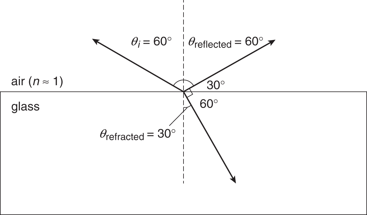
Using n1 sin θ1 = n2 sin θ2, we have
1 sin 60°=n2 sin 30° 32=n2(12) 3=n2
15. D
Light can be split into its component colors by dispersion, such as that through a prism, eliminating (A). Diffraction by a diffraction grating will also separate colors by their wavelengths, eliminating (B). The refraction of light within a thin film also leads to light dispersion as the different colors are refracted at slightly different angles in the film, eliminating (C). A mirror with significant aberration could lead to a separation of light into its component colors, but we are told that this is an ideal mirror. Thus, (D) is the correct answer.
GO ONLINE
Consult your online resources for additional practice.
EQUATIONS TO REMEMBER
(8.1) Speed of light from frequency and wavelength: c = fλ
(8.2) Law of reflection: θ1 = θ2
(8.3) Optics equation: 1f=1o+1i=2r
(8.4) Magnification: m=−io
(8.5) Index of refraction: n=cv
(8.6) Snell’s law: n1 sin θ1 = n2 sin θ2
(8.7) Critical angle: θc=sin−1(n2n1)
(8.8) Lensmaker’s equation: 1f=(n−1)(1r1−1r2)
(8.9) Power: P=1f
(8.10) Focal length of multiple lens system: 1f=1f1+1f2+1f3+⋅⋅⋅+1fn
(8.11) Power of multiple lens system: P = P1 + P2 + P3 + ··· + *P**n*
(8.12) Magnification of multiple lens system: m = m1 × m2 × m3 × ··· × *m**n*
(8.13) Positions of dark fringes in slit–lens setup: a sin θ = nλ
(8.14) Positions of dark fringes in double-slit setup: dsinθ=(n+12)λ
SHARED CONCEPTS
Behavioral Sciences Chapter 2
Sensation and Perception
Biochemistry Chapter 3
Nonenzymatic Protein Function and Protein Analysis
Organic Chemistry Chapter 2
Isomers
Organic Chemistry Chapter 11
Spectroscopy
Physics and Math Chapter 7
Waves and Sound
Physics and Math Chapter 9
Atomic and Nuclear Phenomena