Introduction
Chapter 18 Cell Organization and Movement II: Microtubules and Intermediate Filaments Newt lung cell in mitosis stained for centrosomes (magenta), microtubules (green), chromosomes (blue), and keratin intermediate filaments (red).
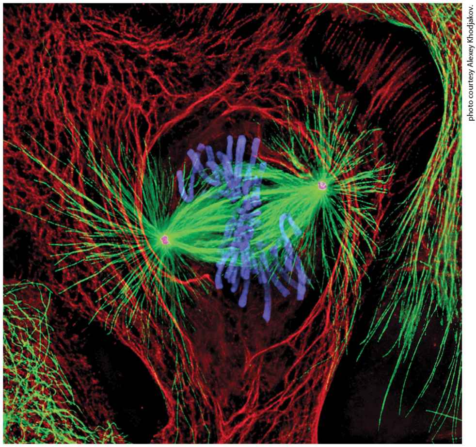
[Reprinted by permission of Nature Publishing Group, from A. Khodjakov, “Olympus/Nature competition: A 1, 2, 3 in Light Microscopy,” Nature, 2000, 408:423–424; permission conveyed through Copyright Clearance Center, Inc.]
18.3 Regulation of Microtubule Structure and Dynamics
18.4 Kinesins and Dyneins: Microtubule-Based Motor Proteins
18.5 Cilia and Flagella: Microtubule-Based Surface Structures
18.8 Coordination and Cooperation Between Cytoskeletal Elements As we learned in the previous chapter, three types of filaments make up the cytoskeleton in an animal cell: microfilaments, microtubules, and intermediate filaments. Why have these three distinct types of filaments evolved? It seems likely that their physical properties are suited to different functions. In Chapter 17, we described how actin microfilaments are often cross-linked into networks or bundles to form mechanically strong yet flexible and dynamic structures and to serve as tracks for the many different classes of myosin motors. Similarly, microtubules are stiff tubes that can exist as a single structure, extending up to in cells, or in bundled arrangements such as those seen in specialized cell-surface structures like cilia and flagella. As a consequence of their tubular design, microtubules are able to generate pulling and pushing forces without buckling, a property that allows single tubules to extend long distances within a cell and bundles to slide past each other, as occurs in flagella and in the mitotic spindle. Microtubules’ ability to extend long distances in the
cell, together with their intrinsic polarity due to the same orientation of subunits along a microtubule, is exploited by microtubule-dependent motors, which use them as tracks for long-range transport of organelles. Microtubules can be highly dynamic — assembling and disassembling rapidly from their ends — and can thus provide the cell with the flexibility to alter microtubule organization as needed. In contrast to microfilaments and microtubules, intermediate filaments have great tensile strength and have evolved to withstand much larger stresses and strains. With properties akin to strong molecular ropes, they are ideally suited to endow both cells and tissues with structural integrity and to contribute to cellular organization. Intermediate filaments do not have an intrinsic polarity as microfilaments and microtubules do, so it is not surprising that there are no motor proteins that use intermediate filaments as tracks. Although we discuss microtubules and intermediate filaments together in this chapter — and although their localization in the cytosol can look superficially quite similar — we will see that their dynamics and functions are very different. A summary of the similarities and differences among these three filament systems is shown in Figure 181.
FIGURE 18-1 Overview of the physical properties and functions of the three filament systems in animal cells. (a) Biophysical and biochemical properties (orange) and biological properties (green) are shown for each filament type. The micrographs (b–d) show examples of each filament type in a particular cellular context, but note that microtubules also make up other structures, and that intermediate filaments also line the inner surface of the nucleus. (b) Cultured cells stained for actin (green) and sites of actin attachment to the substratum (orange). (c) Localization of microtubules (green) and the Golgi complex (yellow). Notice the central location of the Golgi complex, which is collected there by transport along microtubules. (d) Localization of cytokeratins (red), a type of intermediate filament, and a component of desmosomes (yellow) in epithelial cells. Cytokeratins from individual cells are attached to each other through the desmosomes.
Description The chart labeled (a) lists structures and actions of the three main filament systems. The first column titled microfilaments. The list below, reading from top to bottom reads: actin binds A T P, form rigid assembly from a large number of locations, regulated assembly from a large number of locations, highly dynamic, polarized, tracks for myosins, and contractile machinery and network at the cell cortex. The second column is titled microtubules. The list below, reading from top to bottom reads: alpha-betatubulin binds G T P, rigid and not easily bent, regulated assembly from a small number of locations, highly dynamic, polarized, tracks for kinesins and dyneins, organization and long-range transport of organelles. The third column is titled intermediate filaments. The list below, reading from top to bottom, reads: I F subunits don't bind a nucleotide, great tensile strength, assembled onto pre-existing filaments, less dynamic, unpolarized, no motors, and cell and tissue integrity. The fluorescence electron micrograph labeled (b) shows a group of green lines with orange markings on them. The fluorescence electron micrograph labeled (c) shows a bright yellow center surrounded by a web of thin green lines. The fluorescence electron micrograph labeled (d) shows several oval structures each enclosed by a group of thin red lines which are in turn outlined by tiny yellow structures. This chapter covers five main topics. First, we discuss the structure and dynamics of microtubules and their motor proteins. Second, we examine how microtubules and their motors contribute to the movement of cilia and flagella. Third, we discuss the role of microtubules in the mitotic spindle — a molecular machine that has evolved to accurately segregate duplicated chromosomes. Fourth, we explore the roles of the different classes of intermediate filaments that provide structure to the nuclear
envelope as well as strength and organization to cells and tissues. Although we consider microtubules, microfilaments, and intermediate filaments individually, the three filament systems do not act independently of one another, and we consider some examples of this interdependence in the last section of the chapter.
18.1 Microtubule Structure and Organization
18.1 Microtubule Structure and Organization In the early days of electron microscopy, cell biologists noted long tubules in the cytoplasm that they called microtubules. Morphologically similar microtubules were seen making up the fibers of the mitotic spindle, as components of axons, and as the structural elements in cilia and flagella (Figure 18-2a, b). Careful examination of single microtubules from various sources in transverse section indicated that they were all made up of 13 longitudinal repeating units (Figure 18-2c), now called protofilaments, suggesting that these various microtubules shared a common structure. Microtubules purified from brain were found to consist of a major protein, tubulin, together with associated proteins. Purified tubulin alone can assemble into a microtubule under favorable conditions, proving that tubulin is the structural component of the microtubule. Associated proteins help mediate the assembly, dynamics, and function of microtubules. In this section, we consider the general structure and organization of microtubules before turning to a more detailed discussion of their dynamics and regulation in Sections 18.2 and 18.3.
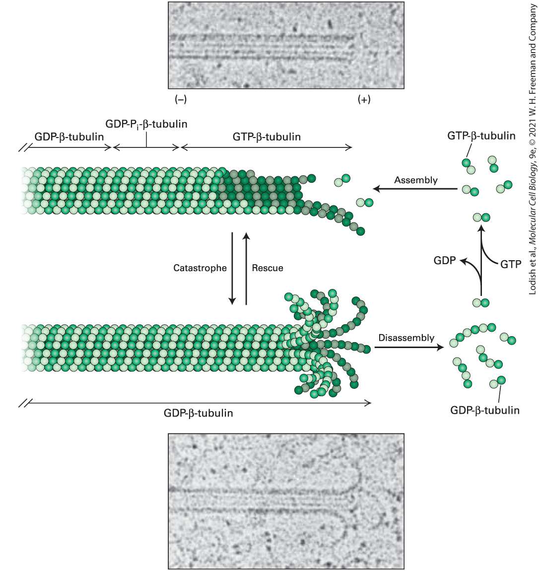
FIGURE 18-2 Microtubules are found in many different locations, and all have similar structures. (a) Surface of the ciliated epithelium lining a rabbit oviduct viewed in a scanning electron microscope. Beating cilia, each of which has a core of microtubules, propel eggs down the oviduct. (b) Microtubules and intermediate filaments in a quick- frozen and deep-etched frog axon visualized in a transmission electron microscope. (c) High-magnification view of a single microtubule showing the 13 repeating units known as protofilaments. [Part (b) N. Hirokawa, 1982, J. Cell Biol. 94(1): 129–142; https://doi.org/10.1083/jcb.94.1.129. Part (c) Republished with permission from John Wiley and Sons, Inc., from H. Sosa and D. Chrétien, 1998, “Relationship Between Moiré Patterns, Tubulin Shape, and Microtubule Polarity,” Cytoskeleton 40(1):38–43; permission conveyed through Copyright Clearance Center, Inc.] Description The micrograph labeled (a) shows brush-like cilia lining cells. The cilia are labeled. The illustration labeled (b) shows a neuron which has a long axon. An electron micrograph shows microtubules in an axon, and a blue square surrounds an area that is
Microtubule Walls Are Polarized Structures Built from αβ-Tubulin Dimers
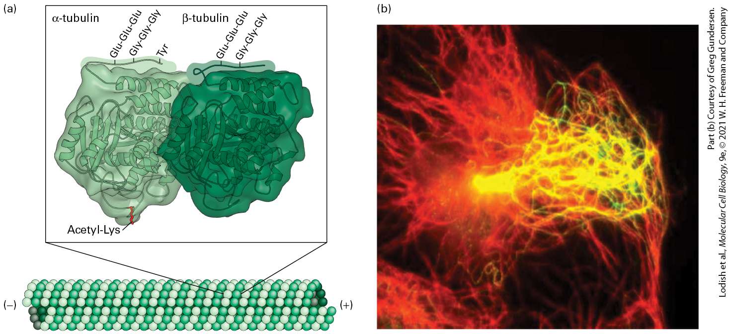
highlighted in the micrograph. In the micrograph, microtubules and intermediate filaments are labeled. They are tubular structures. The electron micrograph labeled (c) shows a section through a microtubule, showing the 13 repeating protofilament subunits. It has a wheel- like structure. Microtubule Walls Are Polarized Structures Built from αβ-Tubulin Dimers Tubulin isolated in a pure and soluble form consists of two closely related subunits called α- and β-tubulin, each with a molecular weight of about 55,000 Da. The building block of a microtubule is an αβ-tubulin dimer. Genomic analyses reveal that genes encoding α- and β-tubulins are present in all eukaryotes and that the number of genes has expanded considerably in multicellular organisms. For example, budding yeast has two genes specifying α-tubulin and one for β-tubulin, whereas the soil nematode Caenorhabditis elegans has nine genes encoding α-tubulin and six for β-tubulin. In addition to α- and β-tubulin, all eukaryotes also have genes specifying a third tubulin, γ-tubulin, which is involved in microtubule assembly, as we will see shortly. Additional isoforms of tubulin have also been discovered that are present only in organisms that possess cellular structures called centrioles and basal bodies, suggesting that these tubulin isoforms are important for those structures. As we’ll learn in this chapter, centrioles and basal bodies are specialized structures that nucleate and organize microtubule assembly.
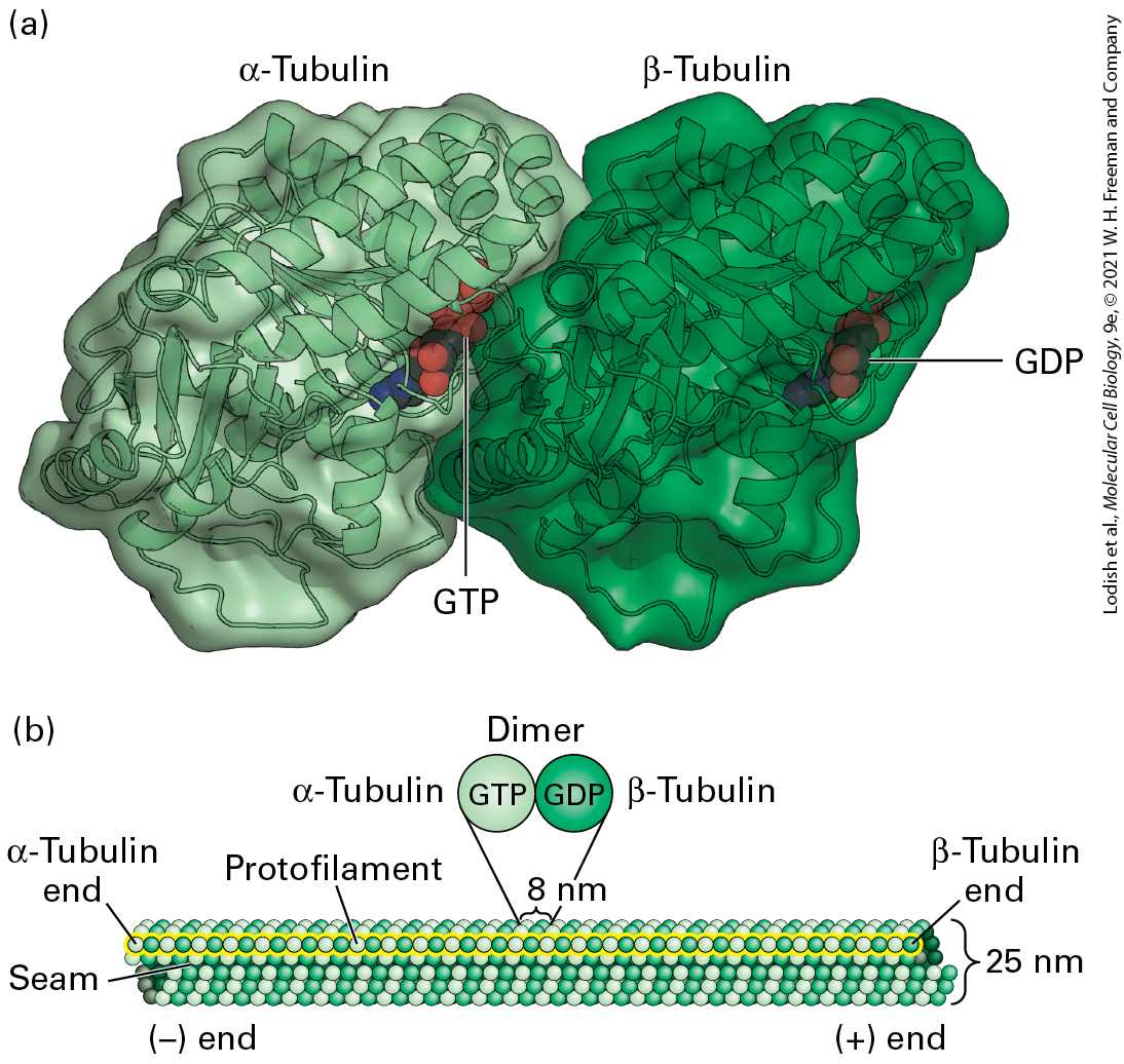
The α- and β-subunits of the tubulin dimer can each bind one molecule of GTP (Figure 18-3a). The GTP in the α-tubulin subunit is never hydrolyzed and is trapped by the interface between the α- and β-subunits. By contrast, the GTP-binding site on the β-subunit is at the surface of the dimer. GTP bound by the β-subunit can be hydrolyzed, and the resulting GDP can be exchanged for free GTP. Under appropriate conditions, soluble tubulin dimers can assemble into microtubules (Figure 18-3b). As we saw in
Chapter 17 for the polymerization of actin, ATP–G-actin is preferentially added to one end of the filament, designated the end because it is the end favored for assembly. Once incorporated into the filament, the bound ATP is hydrolyzed to ADP and . In a similar manner, tubulin dimers in which the β-subunit has bound GTP are added preferentially to one end of the microtubule, also designated the end. As we will see, the GTP is hydrolyzed once tubulin is incorporated into the microtubule and this has dramatic effects on the behavior of the microtubule end.
FIGURE 18-3 Structure of tubulin dimers and their organization into microtubules. (a) Ribbon diagram of the tubulin dimer. The GTP bound to the α-tubulin monomer is nonexchangeable, whereas the GDP bound to the β-tubulin monomer is exchangeable with free GTP. (b) The organization of tubulin subunits in a microtubule. The dimers are aligned end to end into protofilaments, which pack side by side to form the wall of the microtubule. The protofilaments are slightly staggered so that α-tubulin in one protofilament is in contact with α-tubulin in the neighboring protofilaments, except at the seam, where an α-subunit contacts a β-subunit. The microtubule displays a structural polarity in that subunits are added preferentially at the end where β-tubulin monomers are exposed. This end of the microtubule is known as the end. [Part (a) Data from E. Nogales et al., 1998, Nature 391:199, PDB 1D 1tub.]
Description The illustration labeled (a) shows the three-dimensional ribbon structure and surface structure of the alpha and beta tubulin complex. The ribbon structure of alpha – tubulin is bound to a space-filling model of G T P whereas the ribbon structure of beta – tubulin is bound to a space-filling model of G D P. The illustration labeled (b) shows a microtubule composed of tubulin subunits. The microtubule is made up of lines of tubulin units stacked together, which are represented by spheres of two colors (alpha and beta tubulin units) arranged alternatively to form a tubular structure. The negative end is labeled as the alpha-tubulin end, and the positive end is labeled the beta-tubulin end. Each tubulin dimer, composed of alpha and beta tubulins is 8 nanometers is length and is attached to G T P and G D P respectively. A protofilament is represented by a linear arrangement of tubulin dimers. A microtubule is composed of 13 laterally associated protofilaments, which form a tubule whose external diameter is about 25 nm (see Figure 18-3b). Each of the 13 protofilaments is a string of αβ-tubulin dimers, longitudinally arranged so that the subunits alternate along a protofilament, with each subunit type repeating every 8 nm. Because the αβ-tubulin dimers in a protofilament are all oriented in the same way, each protofilament has an α-subunit at one end and a β-subunit at the other — thus the protofilaments have an intrinsic polarity. In a microtubule, all the laterally associated protofilaments have the same polarity, so the microtubule also has an overall polarity. The end with exposed β-subunits is the end, while the end with exposed α-subunits is the end. In microtubules, the heterodimers in adjacent protofilaments are staggered slightly, forming tilted rows of α- and β-tubulin monomers in the microtubule wall. If you follow a row of β-subunits, for example, spiraling
around a microtubule for one full turn, you will end up precisely three subunits up the protofilament, abutting an α-subunit. Thus all microtubules have a single longitudinal seam, where an α-subunit in one protofilament meets a β-subunit in the adjacent protofilament. Most microtubules in a cell consist of a simple tube, a singlet microtubule, built from 13 protofilaments. In rare cases, singlet microtubules contain more or fewer protofilaments. For example, certain microtubules in the neurons of nematode worms contain 11 or 15 protofilaments. In addition to this simple singlet structure, doublet or triplet microtubules are found in specialized structures such as cilia and flagella (doublet microtubules) and centrioles and basal bodies (triplet microtubules), structures we will explore later in the chapter. Each doublet or triplet contains one complete 13-protofilament microtubule (called the A tubule) and one or two additional tubules (B and C) consisting of 10 protofilaments each (Figure 18-4).
FIGURE 18-4 Singlet, doublet, and triplet microtubules. In cross section, a typical microtubule, a singlet, is a simple tube built from 13 protofilaments. In a doublet microtubule, an additional set of 10 protofilaments forms a second tubule (B) by fusing to
Microtubules Are Assembled from MTOCs to Generate Diverse Configurations
the wall of a singlet (A) microtubule. Attaching another 10 protofilaments to the (B) tubule of a doublet microtubule creates a (C) tubule and a triplet structure. Description The illustration shows a singlet microtubule as found in the cytoplasm. It is made of 13 small tubular structures called protofilaments bound to each other to form a tube with a hollow space inside. A doublet arrangement of microtubules, as found in cilia and flagella, shows a single tube, marked A, merged with another tube, marked B. Tube B is composed of 10 protofilaments, the remaining 3 being shared with those of the A tube which has 13 protofilaments. A triplet arrangement of microtubules, as found in basal bodies and centrioles, shows three tubes merged together. The A tube is a complete tube. The b tube shares three of the a tubes units with 10 of its own to form the second tube, and the C tube is attached to the B tube in the same manner as the b tube to the A tube. Microtubules Are Assembled from MTOCs to Generate Diverse Configurations Once tubulin had been identified as the major structural component of microtubules, antibodies to tubulin could be generated and used in immunofluorescence microscopy to localize microtubules in cells (Figure 18-5a, b). This approach, coupled with electron microscopy, revealed that microtubules are assembled from specific sites in the cell.
FIGURE 18-5 Microtubules are assembled from microtubule organizing centers (MTOCs). (a–b) The distribution of microtubules in cultured cells, as seen by immunofluorescence microscopy using antibodies to tubulin, in an interphase cell (a) and a cell in mitosis (b). (c–f) Diagrams of the distributions of microtubules in various cells and structures. All of these microtubules are assembled from distinct MTOCs. (c) In an interphase cell, the MTOC is called a centrosome (the nucleus is indicated by a blue oval). (d) In a mitotic cell, the two MTOCs are called spindle poles (the chromosomes are shown in blue). (e) In a neuron, microtubules in both axons and dendrites are assembled from an MTOC in the cell body and then released from it. (f) The microtubules that make up the shaft of a cilium or flagellum are assembled from an MTOC known as a basal body. The polarity of microtubules is indicted by and . Description The electron micrograph labeled (a) shows an interphase cell with a bright white center with thin long hair-like microtubules spreading out from it. The electron micrograph labeled (b) shows two distinct sets of thin long hair-like microtubules originating from the bright white poles of the cell. The illustration labeled (c) shows microtubules in a cell in interphase. The negative ends of tubular structures called microtubules are connected to a small oval structure labeled centrosome. The microtubules extend outward from this point. A nucleus is represented by a big oval structure.
The illustration labeled (d) shows the arrangement of tubular structures called microtubules in a cell undergoing mitosis. The centromeres are now labeled spindle poles and two are present at each cell pole. The microfilaments extend outward, attached to the spindle poles by the negative ends. The positive ends of the fibers meeting in the center of the cell for attachment to four chromosomes. The illustration labeled (e) shows the distribution of microtubules in a neuron. Microtubules assemble from the microtubule organizing center and are release into the axon and dendrites. The cell body has an oval structure labeled nucleus. The illustration labeled (f) shows microtubules in a cilium. The microtubules extend from the basal body of the cilium. Spontaneous nucleation of microtubules is such an energetically unfavorable reaction that it does not play a significant role in microtubule assembly in vivo. Rather, all microtubules are nucleated from structures known as microtubule-organizing centers, or MTOCs. The centrosome is the main MTOC in animal cells. During interphase, the centrosome is generally located near the nucleus, producing an array of microtubules with their ends radiating toward the cell periphery (Figure 18-5c). In most cases, the end of the microtubule stays anchored in the centrosome. This radial array provides tracks for microtubule-based motor proteins to organize and transport membranebounded compartments, such as those constituting the secretory and endocytic pathways. During mitosis, cells reorganize their microtubules to form a bipolar spindle extending from two centrosomes, also known as spindle poles, that can accurately segregate copies of the duplicated chromosomes (Figure 18-5d). Neurons, in another example, have long processes called axons, in which organelles are transported in both
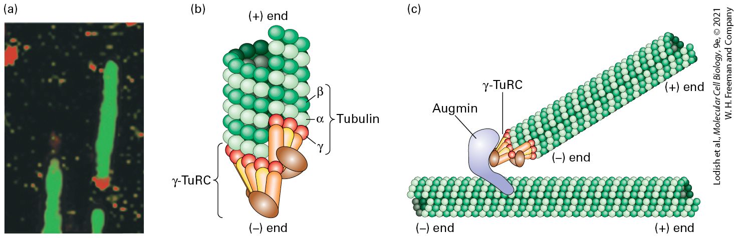
directions along microtubules (Figure 18-5e). The microtubules in axons, which can be as long as 1 m, are not continuous and have been released from the MTOC, but nevertheless all have the same polarity. The microtubules in shorter processes, called dendrites, have mixed polarity, although the functional significance of this difference is not clear. In cilia and flagella (Figure 18-5f), microtubules are assembled from an MTOC called a basal body. As we mention later, plants do not have centrosomes and basal bodies; they use other mechanisms to nucleate the assembly of microtubules. Electron microscopy shows that each centrosome in an animal cell consists of a pair of orthogonally arranged cylindrical centrioles surrounded by amorphous material called pericentriolar material (Figure 18-6a). Centrioles, which are about long and in diameter, are highly organized and stable structures that consist of nine triplet microtubules (Figure 18-6b, c). The centrioles themselves do not nucleate the cytoplasmic microtubule array. Instead, factors in the pericentriolar material do. A critical component is the γ-tubulin ring complex (γ-TuRC) (Figure 18-6b and Figure 18-7), which is located in the pericentriolar material and consists of many copies of γ-tubulin associated with several other proteins. The γ-TuRC acts as a helical template to bind αβ-tubulin dimers for the formation of a new microtubule, whose end is associated with γ-TuRC and whose end is free for further assembly.
FIGURE 18-6 Structure of centrosomes. (a) Thin section of an animal-cell centrosome showing the two centrioles at right angles to each other, surrounded by pericentriolar material (arrows). (b) Diagram of a centrosome showing the mother and daughter centrioles, each of which consists of nine linked triplet microtubules, embedded in pericentriolar material that contains γ-TuRC nucleating structures. The mother centriole is distinct from the daughter as it has distal appendages (blue spheres). (c) A tomographic image of a section through a daughter centriole of the alga Chlamydomonas. A protein called Sas6 can self-assemble into a ninefold symmetrical cartwheel structure to serve as a template for the daughter centriole (purple structure). It is later removed as the centriole matures. (d) Immunofluorescence micrograph showing the microtubule array (green) in a cultured animal cell and the location of the MTOC, using an antibody to a centrosomal protein (yellow).
[Part (a) Reprinted by permission from Nature Publishing Group, from G. Sluder, 2005, “Two-Way Traffic: Centrosomes and the Cell Cycle,” Nat. Rev. Mol. Cell Biol. 6:743–748; permission conveyed through Copyright Clearance Center, Inc. Part (c) Data from P. Guichard et al., 2013, Curr. Biol. 23:1620, EMD-2329 and EMD-2330.] Description An electron micrograph labeled (a) shows the mother centriole represented by a dark circular section in the middle and the daughter centriole arranged at 90 degrees to the mother centriole. It is represented by a dark cylindrical structure. Several arrows point to its surroundings. An illustration labeled (b) shows the structure of the centrosome. The mother centriole is composed of a ring of triplet microtubules (tubular structures), with subdistal and distal appendages attached to the outside of the microtubule ring. These appendages represented by spheres with hair like projections at the bottom. Gamma-T u R C is represented by tiny oval rings surrounding the mother centriole. A separate tubular structure is labeled microtubule. The daughter centriole lies at 90 degrees to the mother centriole. It is also made of a ring of triplet microtubules. Both of these structures are suspended in pericentriolar material represented by tiny dots. A tomographic image labeled (c) shows a section of the daughter centriole. It is composed of a ring of triplet microtubules which looks like a gear wheel. An electron micrograph labeled (d) shows thin hair-like green fluorescent microtubules spreading out from two bright yellow colored centrosomal proteins. Basal bodies have a structure similar to centrioles and are the MTOCs found at the base of cilia and flagella. The A and B tubules of their triplet microtubules provide a template for the assembly of the microtubules making up the core structure of cilia and flagella. Later, we discuss the structure of basal bodies in the context of cilia and flagella.
Recent work has uncovered an additional mechanism for the nucleation of microtubules in animal cells, also involving γ-TuRC. A protein complex called the augmin complex, consisting of eight polypeptides, can bind to the sides of existing microtubules, then recruit γ-TuRC and nucleate the assembly of new ones (Figure 18-7c). As we discuss in a later section, the augmin complex contributes to microtubule assembly in the mitotic spindle.
FIGURE 18-7 The γ-tubulin ring complex (γ-TuRC) that nucleates microtubule assembly. (a) Immunofluorescence micrograph in which microtubules assembled in vitro are labeled green and a component of the γ-TuRC is labeled red, showing that it is located specifically at one end of the microtubule. (b) Model of how γ-TuRC nucleates assembly of a microtubule by forming a template corresponding to the end. (c) Diagram of how augmin can bind both γ-TuRC and the side of an existing microtubule to nucleate assembly of a branched microtubule. [Part (a) Reprinted with permission from Nature Publishing Group, from T. J. Keating and G. G. Borisy, 2000, “Immunostructural Evidence for the Template Mechanism of Microtubule Nucleation,” Nat. Cell Biol. 2:352–357; permission conveyed through Copyright Clearance Center, Inc.] Description An electron micrograph labeled (a) and two illustrations labeled (b) and (c) shows microtubules tubules with a gamma-T u R C, a structure of a part of the microtubule
attached to gamma-T u R C, and the attachment of two microtubules. KEY CONCEPTS OF SECTION 18.1 Microtubule Structure and Organization Tubulin is the major structural component of microtubules (see Figure 18-3). Microtubule-associated proteins (MAPs) associate with tubulin and help mediate the assembly, dynamics, and function of microtubules. Free tubulin exists as a dimer in which the α-subunit contains a trapped and nonhydrolyzable GTP and the β-subunit binds an exchangeable and hydrolyzable GTP. αβ-Tubulin assembles into microtubules, each of which is made up of 13 laterally associated protofilaments, with an α-subunit exposed at the end and a β-subunit at the end of each protofilament. In cilia, flagella, centrioles, and basal bodies, doublet and triplet microtubules exist in which the additional microtubules have 10 protofilaments (see Figure 18-4). All microtubules are nucleated from microtubule-organizing centers (MTOCs), and many remain anchored with their ends there. Thus the end away from the MTOC is always the end. The centrosome is the MTOC that nucleates the radial array of microtubules in interphase animal cells. Two centrosomes, or spindle poles, are the MTOCs that nucleate the microtubules of the mitotic spindle in animal cells. Basal bodies are the MTOCs that assemble the microtubules of cilia and flagella (see Figure 18-5). Centrosomes consist of two centrioles and the surrounding pericentriolar material, which contains the γ-TuRC microtubule-nucleating complex (see Figures 18-6 and 18-7).
Individual Microtubules Exhibit Dynamic Instability
18.2 Microtubule Dynamics Microtubules are dynamic structures that can assemble or disassemble rapidly at their ends. Their lifetimes can vary enormously, averaging less than 1 minute for cells in mitosis and about 5–10 minutes for the microtubules that make up the radial array seen in interphase animal cells. Microtubule lifetime is longer in axons and much longer in cilia and flagella. To see how these differences occur, we will look at the dynamic properties of microtubules and how these properties contribute to their cellular organization. Individual Microtubules Exhibit Dynamic Instability Early experiments revealed that most microtubules in animal cells disassemble when the cells are cooled to 4 °C and reassemble when the cells are warmed to 37 °C. Researchers realized that this intrinsic property of microtubules could be exploited to purify their components. Since brain tissue is rich in microtubules, soluble extracts of pig brains were prepared at 4 °C; these clarified extracts were then warmed to 37 °C to induce microtubule assembly. The assembled microtubules were collected into a pellet by centrifugation, separated from the supernatant, and then disassembled by adding buffer at 4 °C. After another cycle of assembly by warming, collection, and disassembly by cooling, researchers recovered
microtubular protein, a collective term for αβ-tubulin and microtubuleassociated proteins (MAPs). They were then able to fractionate the microtubular protein into pure αβ-tubulin and MAPs to study their behaviors separately. Investigators found that polymerization of dimeric αβ-tubulin into microtubules can be catalyzed by the presence of the MAPs. Research on the bulk polymerization properties of microtubular proteins in solution revealed two important things. First, for assembly to occur, the αβ-tubulin concentration must be above the critical concentration ( ), just as we saw for actin polymerization (see Figure 17-8). Second, at αβtubulin concentrations higher than , tubulin dimers are added faster to one end of the microtubule than to the other (Figure 18-8). As with F-actin assembly, the preferred end for assembly, which is the end with β-tubulin exposed, is designated the end. The end has α-tubulin exposed (see
EXPERIMENTAL FIGURE 18-8 Microtubules grow preferentially at the end. A fragment of a microtubule bundle from a flagellum was used as a nucleus for the in vitro
addition of αβ-tubulin. The nucleating flagellar fragment is the thick bundle seen in this electron micrograph, with the newly formed microtubules (MT) radiating from its ends. The greater length of the microtubules at one end, the end, indicates that tubulin subunits are added preferentially to this end. When studying the bulk properties of microtubule assembly by raising the temperature of a tubulin solution from 4 °C to 37 °C, a typical curve reflecting nucleation, elongation, and steady state is observed (Figure 189a). Although one might assume that all microtubules would behave similarly, when researchers explored the behavior of individual microtubules within a population, they found that this was not the case. Individual microtubule behavior was examined in a simple experiment: microtubules were assembled in vitro and then sheared to break them into shorter pieces whose individual lengths could be analyzed by microscopy. Under these conditions, one might expect all the short microtubules either to grow or to shrink, depending on the free tubulin concentration. However, the investigators found that some of the microtubules grew in length, whereas others shortened very rapidly — thus indicating the existence of two distinct populations of microtubules. Further studies showed that individual microtubules could grow and then suddenly experience a catastrophe: an abrupt transition to a shrinking phase during which the microtubule would undergo rapid depolymerization. Moreover, sometimes a depolymerizing microtubule end could go through a rescue and begin growing again (Figure 18-9b). Although this phenomenon was first seen in vitro, analysis of fluorescently labeled tubulin microinjected into live cells showed that microtubules in cells also undergo periods of growth and shrinkage (Figure 18-10). This alternation between growing
and shrinking states is known as dynamic instability. Thus the dynamic life of a microtubule end is determined by the rate of growth, the frequency of catastrophes, the rate of depolymerization, and the frequency of rescues. As we will see, these four features of microtubule dynamics are controlled in vivo. Since the ends of microtubules in animal cells are generally anchored to an MTOC, this dynamism is most relevant to the end of the microtubule.
FIGURE 18-9 Comparison of the assembly properties of a preparation of bulk tubulin compared with the dynamics of an individual microtubule. (a) When pure tubulin above its is warmed from 4 °C to 37 °C to induce polymerization, typical nucleation, elongation, and steady-state phases are seen. (b) However, when individual microtubules in an assembling population are observed in the light microscope and their lengths plotted at different times, they can be seen to grow and shrink in a process known as dynamic instability. Assembly and disassembly each proceed at uniform rates, but there is a big difference between the rate of assembly and that of disassembly, as seen in the different slopes of the lines. Shortening of a microtubule is much more rapid (7 μm/min) than growth (1 μm/min). Notice the abrupt transitions to the shrinkage stage (catastrophe) and to the elongation stage (rescue). [Data from P. M. Bayley, K. K. Sharma, and S. R. Martin, 1994, in J. S. Hyams and C. W. Lloyd, eds., Microtubules, p. 118. New York: Wiley-Liss.] Description
(a)The horizontal axis of the graph represents the total microtubule polymer. It has no units. The vertical axis represents time in minutes ranging from 0 to 90 in intervals of 30. The top of the graph is labeled nucleation for 15 minutes, then elongation for 30 minutes, and steady state for the rest. A curve starts at 0 and slopes upward rapidly until steady state where it plateaus. (b) The horizontal axis of the graph represents microtubule length in micrometers ranging from 0 to 50 in intervals of 10 micrometers. The vertical axis represents time in minutes ranging from 0 to 90 in intervals of 30. The graph shows a zigzag curve that rises and then sharply falls. The increase in microtubule length takes a longer period of time than disassembly, as represented by the gentler gradient of the assembly phase and the sudden reduction in length during the disassembly phase. The peak between assembly and disassembly is labeled catastrophe. The downward peak between disassembly and assembly is labeled rescue. EXPERIMENTAL FIGURE 18-10 Fluorescence microscopy reveals growth and shrinkage of individual microtubules in vivo. Fluorescently labeled tubulin was microinjected into cultured human fibroblasts. The cells were chilled to depolymerize preexisting microtubules into tubulin dimers and were then incubated at 37 °C to allow repolymerization, which incorporated the fluorescent tubulin into all the cells’ microtubules. A region of a cell periphery was viewed in the fluorescence microscope at 0 seconds, 27 seconds later, and 3 minutes 51 seconds later (left to right panels). During this period, several microtubules can be seen to have elongated and shortened. The dots labeled A, B, and C mark the positions of the ends of three microtubules.
[Reprinted with permission from Nature Publishing Group, from P. J. Sammak and G. G. Borisy, 1988, “Direct Observation of Microtubule Dynamics in Living Cells,” Nature, 332:724–726; permission conveyed through Copyright Clearance Center, Inc.] Description The three images are of the same microtubule construction at 0 seconds, 27 seconds, and 3 minutes and 51 second intervals. Three microtubules are labeled A, B, and C. Over the course of the experiment, the A microtubule lengthens then shortens, the B microtubule lengthens, and the C microtubule remains the same length. What is the molecular basis of dynamic instability? If we look carefully at the ends of growing and shrinking microtubules in the electron microscope, we can see that they are quite different. A growing microtubule has a relatively blunt end, whereas a depolymerizing end has highly curved protofilaments peeling off like rams’ horns (Figure 18-11). In fact, the growing microtubule end is not simply a blunt end, but a ragged collection of gently curving protofilaments that then associate laterally to form the cylindrical microtubule with straight protofilaments.
FIGURE 18-11 Dynamic instability depends on the presence or absence of a GTP-βtubulin cap. Images taken in the electron microscope of frozen samples of a growing microtubule (upper) and a shrinking microtubule (lower). Notice that the end of the growing microtubule has a blunter end, whereas the end of the shrinking one has curls like a ram’s horns. As the diagram shows, a microtubule with several GTP-β-tubulin dimers on the end of each protofilament is strongly favored to grow. However, a microtubule with GDP-β-tubulin at the ends forms highly curved protofilaments and will undergo rapid
disassembly. Switches between growing and shrinking phases, called rescues and catastrophes, can occur, and the rate of switching is regulated by associated proteins. [E. M. Mandelkow, E. Mandelkow, and R. A. Milligan, 1991, J. Cell Biol. 114(5): 977–991; https://doi.org/10.1083/jcb.114.5.977.] Description In the first electron micrograph the microtubules appear as a band of dark thin straight lines. The illustration corresponding to it shows a microtubule having a tubular structure made up of alpha and beta tubulin subunits. The first portion of microtubule is labeled G D P-beta-tubulin, the middle portion is labeled G D P- P subscript i-beta- tubulin and the growing portion is also labeled G D P-beta-tubulin. The positive end of the microtubule undergoes G T P- beta- tubulin assembly where a molecule of G D P is released. The end of the growing microtubule becomes blunt shaped. In the second electron micrograph the microtubules appear as a band of dark thin straight lines with one of the ends extending to form curls. The illustration corresponding to it shows a microtubule having a tubular structure made up of alpha and beta tubulin subunits. The entire microtubule is labeled G D P-beta-tubulin. The positive end of the microtubule undergoes G T P- beta- tubulin disassembly where a group of dimers get disassembled. The growing microtubule shows splayed endings. A downward arrow labeled catastrophe and an upward arrow labeled rescue is present between the first and second microtubules. A simple structural difference accounts for the morphology of these two different classes of microtubule ends. Using a GDP analog, researchers have found that artificially made single protofilaments — which are not exposed to lateral interactions — made up of repeating αβ- tubulin dimers containing GDP-β-tubulin are curved, like a ram’s horn. However, artificially made single protofilaments made up of αβ-tubulin dimers in which β-tubulin has a bound GTP analog are only slightly curved. The assembling end of a microtubule contains these slightly
curved nascent protofilaments, giving rise to the gently curved protofilaments characteristic of growing ends (see Figure 18-11). The gently curved protofilaments containing GTP-β-tubulin then zip up by lateral interactions to form straight protofilaments within the microtubule. Such a growing microtubule is said to have a GTP cap. By contrast, shrinking microtubules with highly curled ends are made up of GDP-βtubulin. Therefore, if the GTP molecules in the terminal β-tubulins become hydrolyzed on a microtubule that has stopped growing, a formerly blunt-ended microtubule will curl and a catastrophe will ensue. These relationships are summarized in Figure 18-11. These results have an additional and fascinating implication, but to understand it we must consider the growing microtubule in more detail. The addition of dimers with GTP-β-tubulin to the end of protofilaments on a growing microtubule will generate the GTP cap on each protofilament. These elongated protofilaments then associate by lateral interactions to become straight and form the microtubule wall. This transition from a curved to straight protofilament induces a strained conformation in the tubulin dimer. The interaction between the β-subunit of one dimer and the α-subunit of the next enhances hydrolysis of GTP in the β-subunit to GDP- . The inorganic is then slowly released. In this way, a growing microtubule has a GTP cap, followed by a region in which β-tubulin has , followed by the older region that has just GDP-βtubulin (see Figure 18-11). As we mentioned above, an isolated protofilament containing GDP-βtubulin is curved along its length, so when it is present in a microtubule,
Localized Assembly and Search and Capture Help Organize Microtubules
why doesn’t it break out and peel away? The lateral protofilamentprotofilament interactions in the GTP-β-tubulin cap are sufficiently strong that they do not allow the microtubule to unpeel at its end — and so the protofilaments behind the GTP-β-tubulin cap are constrained from unpeeling (see Figure 18-11). The energy released by GTP hydrolysis in the subunits behind the cap is stored within the lattice as structural strain waiting to be released when the GTP-β-tubulin cap is lost. This implies that if the GTP-β-tubulin cap is lost, the stored energy can do work if some structure, such as a chromosome, is attached to the disassembling microtubule end. As we will see, this stored energy drives the movement of chromosomes during the anaphase stage of mitosis. How can a disassembling microtubule suddenly be rescued to grow again? One possible answer to this perplexing problem has been suggested. Using an antibody that recognizes GTP-β-tubulin but not GDP-β-tubulin, researchers have found that islands of GTP-β-tubulin can persist along the length of an assembled microtubule. It seems likely that when a disassembling microtubule encounters one of these GTP-β-tubulin islands, disassembly pauses, and a rescue may be provoked. Localized Assembly and Search and Capture Help Organize Microtubules We have now presented two major concepts relating to microtubule organization and end dynamics: microtubules are assembled starting from MTOCs, and individual microtubules can undergo dynamic
Drugs Affecting Tubulin Polymerization Are Useful Experimentally and in Treatment of Diseases
instability. Together, these two processes contribute to the distribution of microtubules in cells. In an interphase cell growing in culture, microtubules are constantly being nucleated from the centrosome and spreading out, randomly searching the cytoplasmic space. The frequency of catastrophes and rescues, together with growth and shrinkage rates, determines the length of each microtubule. If the microtubule is subject to a high catastrophe frequency and a low rescue frequency, it will shrink back to the centrosome and disappear, whereas if it has few catastrophes and is readily rescued, it will continue to grow. If the searching microtubule encounters an appropriate target on a cell structure or organelle, the microtubule end may become attached to that structure. Organelle or cell-structure capture by the microtubule can stabilize its end and protect it from catastrophes, whereas unattached microtubules have a greater frequency of disassembly. So the dynamics of the microtubule end is a very important determinant of microtubule life cycle and function. Search and capture is part of the mechanism determining the overall organization of microtubules in a cell. Moreover, by changing the rate of nucleation or local microtubule dynamics and capture sites, a cell can rapidly change its overall microtubule distribution. We will see later that this is what happens as cells enter mitosis. Drugs Affecting Tubulin Polymerization Are Useful
Experimentally and in Treatment of Diseases The conserved nature of tubulins and their essential role in critical processes such as mitosis make them prime targets for both naturally occurring and synthetic drugs that affect polymerization or depolymerization. The first of these drugs was colchicine (present in extracts of the meadow saffron), which binds tubulin dimers so that they cannot polymerize into microtubules. Since most microtubules are in a dynamic state between dimers and polymers, the addition of colchicine sequesters all free dimers in the cytoplasm, resulting in loss of microtubules due to their natural turnover. Treatment of cultured cells with colchicine for a short time results in the depolymerization of all the cytoplasmic microtubules, leaving the more stable tubulin-containing centrosome (Figure 18-12a). When the colchicine is washed out to allow regrowth of the microtubules, they can be seen to grow from the centrosome, revealing its ability to nucleate the assembly of new microtubules (Figure 18-12b).
EXPERIMENTAL FIGURE 18-12 Microtubules grow from the MTOC. To investigate the assembly of microtubules in vivo, a cultured fibroblast was treated with colchicine until almost all the cytoplasmic microtubules were disassembled. The cell was then stained with antibodies to tubulin and viewed by immunofluorescence microscopy (a). In a separate experiment, the colchicine was washed out to allow reassembly of the microtubules. Panel (b) shows the first stages of reassembly, revealing microtubules growing from the MTOC in the central region above the nucleus (dark area). Note in panel (a) the remaining primary cilium (arrowhead; discussed in Section 18.5) associated with the centrosome, which is not depolymerized by colchicine treatment under these conditions. Note also the fluorescence from the cytoplasm, which is from unpolymerized αβ-tubulin dimers. [E. M. Mandelkow, E. Mandelkow, and R. A. Milligan, 1991, J. Cell Biol. 114(5):977–991; https://doi.org/10.1083/jcb.114.5.977.] Description The immunofluorescence micrograph labeled (a) shows a dark oval structure, which is the nucleus surrounded by a cell represented in white. There is a spiky structure present at the edge of the dark oval structure. The immunofluorescence micrograph labeled (b) shows a dark oval structure, which is the nucleus surrounded by a cell represented in white. There is a web of thin
microtubules extending out from a central bright white area which is the M O T C. Colchicine has been used for hundreds of years to relieve the joint pain of acute gout. A famous patient was King Henry VIII of England, who was treated with colchicine to relieve this ailment. A low level of colchicine relieves the inflammation caused in gout by reducing the microtubule dynamics of white blood cells, rendering them unable to migrate efficiently to the site of inflammation. In addition to colchicine, a number of other drugs bind the tubulin dimer and restrain it from forming polymers. These drugs include podophyllotoxin (from juniper) and nocodazole (a synthetic drug). Taxol, a plant alkaloid from the Pacific yew tree, binds microtubules and stabilizes them against depolymerization. Because taxol stops cells from dividing by inhibiting mitosis, it has been used to treat some cancers, such as those of the breast and ovary, where the cells are especially sensitive to the drug. KEY CONCEPTS OF SECTION 18.2 Microtubule Dynamics Individual microtubule ends can undergo dynamic instability, showing alternating periods of growth or rapid shrinkage (see Figure 18-10). Most of the β-tubulin in microtubules contains bound GDP. In growing microtubules, the ends have a cap of many dimers containing GTP-β-tubulin, resulting in slightly splayed ragged protofilament ends. Shrinking microtubules have lost the cap, causing the protofilaments at the end, containing GDP-β-tubulin, to peel outward and disassemble (see Figure 18-11).
Growing microtubules store the energy derived from GTP hydrolysis in the microtubule lattice, so they have the potential to do work when disassembling. Microtubules assembled from the centrosome and exhibiting dynamic instability can search the cytoplasm for structures or organelles with appropriate targets and capture them, which results in stabilization of the microtubule end. In this way, assembly coupled with search and capture can contribute to the overall distribution of microtubules in a cell.
18.3 Regulation of Microtubule Structure and Dynamics
18.3 Regulation of Microtubule Structure and Dynamics The regulation of microtubule structure and dynamics is critical for proper cell function. As we will see later in this chapter, microtubules are the major organizers of organelles in animal cells, and the stability and dynamics of microtubules are tailored for the specific function of the cell at any given time. For example, the dynamics of microtubules increase dramatically as a cell enters mitosis to allow the cell to build the mitotic spindle. The wall of a microtubule is built from αβ-tubulin dimers, and highly purified αβ-tubulin will assemble in vitro into microtubules. Assembly of microtubules in vitro is greatly enhanced by the presence of certain microtubule-associated proteins (MAPs). MAPs regulate microtubule dynamics in a number of ways. Broadly, some stabilize microtubules, other MAPs destabilize them, and a third group of MAPs alters the growth properties of microtubules. We discuss the various examples of MAPs in this section, which are summarized in Table 18-1.
TABLE 18-1 • Summary of the Microtubule-Associated Proteins (MAPs) Discussed in This Section Name Function MAP2, MAP4, Tau Stabilizing
Microtubules Are Stabilized by Side-Binding Proteins
TIP suppresses end catastrophes Kinesin-13 Promotes end disassembly Op18/Statmin Promotes end disassembly Katanin AAA ATPase severing Microtubules Are Stabilized by SideBinding Proteins Several classes of proteins stabilize microtubules, many of which show cell-type-specific expression. Among the best-studied MAPs are members of the tau family of proteins, which includes tau itself as well as proteins called MAP2 and MAP4. Tau and MAP2 are neuronal proteins, while MAP4 is expressed by other cell types and is generally not present in neurons. These proteins have a modular design with two key domains. The first domain consists of a positively charged 18-residue sequence, repeated three to four times, that binds to the negatively charged microtubule surface. The second domain projects outward at a right angle from the microtubule (Figure 18-13b). Tau proteins stabilize microtubules and also act as spacers between them. MAP2 is found only in dendrites of neurons, where it forms fibrous cross-bridges between microtubules and links microtubules to intermediate filaments. Tau, which is much smaller than
most other MAPs, is present in both axons and dendrites. The basis for this specificity is still a mystery.
EXPERIMENTAL FIGURE 18-13 Spacing of microtubules depends on the length of the projection domains of microtubule-associated proteins. (a) Insect cells transfected to express MAP2, which has a long arm, or to express tau protein, which has a short arm, grow long axon-like processes. These electron micrographs show cross sections through the processes induced by the expression of MAP2 (left) and tau (right) in transfected cells. Note that the spacing between microtubules (MTs) in MAP2-containing cells is greater than in tau-containing cells. Both cell types contain approximately the same number of microtubules, but the effect of MAP2 is to enlarge the caliber of the axon-like process. (b) Diagrams of association between microtubules and MAPs. Note the difference between the lengths of the projection domains in MAP2 and in tau. [Part (a) Reprinted by permission from Nature Publishing Group, from J. Chen et al., 1992, “Projection Domains of MAP2 and Tau Determine Spacings Between Microtubules in Dendrites and Axons,” Nature, 360(6405):674–676; permission conveyed throght Copyright Clearance Center, Inc.] Description One of the two electron micrographs labeled (a) shows a cell represented by a dark irregular shaped structure inside which there are tiny circles evenly spaced out. These tiny circles are labeled M T s (microtubules). The other electron micrograph shows a circular cell inside which there is a dark oval structure above which there are tiny circles with fewer gaps in between them as compared to the first micrograph. These tiny circles are labeled M T s The illustration labeled (b) shows two vertical microtubules made up of lines of tubulin units stacked together, which are represented by spheres of two colors arranged alternatively. The first microtubule is attached to a M A P 2 protein approximately 50 nanometers in length. M A P 2 has a rod- like structure with segments attached to the side of the microtubule with a curly hair like projection that floats freely. The second microtubule is attached to t a u protein which has a similar structure to M A P 2 except the hair-like curly projection is less than 25 nanometers in length. When stabilizing MAPs coat the outer wall of a microtubule, they can increase the growth rate of microtubules or reduce catastrophe frequency.
+TIPs Regulate the Properties and Functions of the Microtubule (+) End
In many cases, the activity of the MAPs is regulated by the reversible phosphorylation of their projection domains. Phosphorylated MAPs are unable to bind to microtubules; thus phosphorylation promotes microtubule disassembly. For example, microtubule-affinity-regulating kinase (MARK/Par-1) is a key modulator of tau proteins. Some MAPs, including MAP4, are also phosphorylated by a cyclin-dependent kinase (CDK) that plays a major role in controlling the activities of proteins in the course of the cell cycle (see Chapter 19). TIPs Regulate the Properties and Functions of the Microtubule End In addition to the side-binding MAPs, MAPs that associate with a region near the end of microtubules have been identified. In many cases, they associate only with ends that are growing (Figure 18-14a, b). The MAPs in this class are known as TIPs, for plus-end tracking proteins. The best studied of these is between the TIP called EB1 (end binding-1) and the related EB3 and a growing microtubule end. High-resolution microscopy has revealed that EB1 associates with the microtubule tip just behind the GTP-β-tubulin-containing cap, in the region containing (see Figure 18-11). Binding of EB1 induces a twist in the tubulin subunits that is thought to transmit a long-range mechanical signal to enhance GTP hydrolysis in the cap. Thus at least in some in vitro studies EB1 is a destabilizer of microtubules leading to a higher rate of catastrophe (Figure 18-14c). Some TIPs associate with the end either
by binding EB1 or by requiring EB1 for their association with the end, and are generally said to be “hitchhiking” on EB1 (Figure 18-14d). EXPERIMENTAL FIGURE 18-14 The TIP protein EB1 associates near the ends of microtubules. (a) A cultured cell stained with antibodies to tubulin (red) and the TIP protein EB1 (green). EB1 is enriched in the region of the microtubule end. (b) Edge of a live cell expressing EB3-GFP (green) and mCherry-α-tubulin (red). EB3, which is closely related to EB1, is found very close to the end of some microtubules. (c) EB3-GFP selectively associates with growing microtubules, as seen in this so-called kymograph. In this figure, the dynamics of a single microtubule (red) and EB3 (green) in a live cell like that shown in part (b) is followed by taking the same region from sequential frames of a movie and lining them up top to bottom. At the top, one sees the start of the movie with the microtubule capped by EB3. Moving down the figure, one can track the dynamics of the microtubule over time as it grows and shrinks. When the microtubule grows, it remains capped by EB3. When microtubule growth pauses or the microtubule shrinks, EB3 is no longer associated with the end, but it becomes reassociated when growth resumes. A
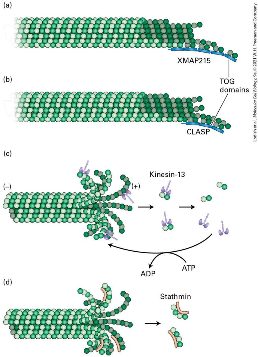
diagrammatic summary of the microtubule dynamics overlies the kymograph. (d) A possible mechanism for EB1 binding to a growing microtubule and “hitchhiking” by other proteins on EB1. Description An electron micrograph labeled (a) shows a circular pattern of red lines labeled as tubulin. The tubulins have green spots at their ends, labeled E B 1 or E B 3. An electron micrograph labeled (b) shows the edge of a cell that has the red lines in a web with the green dots mostly at the ends nearest the edge of the cell. A kymograph labeled (c) shows the edge of the cell as the green E B 1 or E B 3 is now rows of green along the edge. A downward arrow at the left of this image reads “time 387 seconds.” The vertical arrow below the image is labeled “distance.” The green lines have a solid line arrow labeled growth. After each line, a red portion of the edge has a dotted line labeled shortening. The edge looks wavy to a point with a short downward red line which is labeled Pause. Right after the pause is another dotted line. At each point where the green line ends, a letter C is labeled catastrophe. At each point where the dotted lines end is a letter R labeled rescue. An illustration labeled (d) shows the tubulin as a cylinder composed of white and green circles. E B 1 is a light tan structure with a tail and a head that attaches to the tubulin at the side. Two oval structures at the bottom are attached to E B 1 structures and are labeled other plus T I P s hitchhiking on E B 1. The portion of the tubulin with E B 1 on it is also labeled G D P-P subscript i-beta tubulin, and the portion to the right is labeled G T P-beta-tubulin. The positive and the negative ends of the microtubules are labeled. Other TIPs, that bind independently of EB1, can promote microtubule growth either by enhancing assembly or by suppressing catastrophes. For example, a protein called XMAP215 contains five so-called TOG domains. These domains have the ability to bind free αβ-tubulin dimers as well as the gently curved regions of protofilaments at the growing end of a microtubule. By binding to the growing end and bringing more αβ-tubulin
dimers there, XMAP215 effectively increases the local αβ-tubulin concentration to enhance microtubule assembly (Figure 18-15a). Another class of proteins, called CLASPs, have related TOG domains but do not enhance assembly. Instead, they bind to the gently curved growing end and suppress catastrophes (Figure 18-15b). Another function of TIPs is to link the microtubule end to other cellular structures, such as the cell cortex, F-actin, and as we will see later during our discussion of mitosis, chromosomes; a key feature of this dynamic system is that when a TIP at the end of a searching microtubule encounters an appropriate target, the microtubule can become captured and stabilized. Yet other TIPs link microtubule ends to membranes; for example, linkage to the endoplasmic reticulum transmembrane protein STIM promotes microtubule-dependent extension of the tubular endoplasmic reticulum.
FIGURE 18-15 Proteins that regulate the ends of microtubules. (a) The protein XMAP15 has five TOG domains, some of which bind the gently curved protofilaments of a growing microtubule end, whereas others bind αβ-tubulin dimers to enhance gowth. (b) CLASP also has TOG domains that stabilize the ends of microtubules to suppress catastrophes. (c) A member of the kinesin-13 family enriched at a microtubule end can enhance the disassembly of that end. [Although depolymerization of the end is shown, kinesin-13 can also depolymerize the end.] These proteins are ATPases, and ATP enhances their activity by dissociating them from the αβ-tubulin dimer. (d) Op18/stathmin binds selectively to curved protofilaments and enhances their dissociation from a microtubule end. Description A microtubule is made up of lines of tubulin units stacked together, which are represented by spheres of two colors (alpha and beta tubulin units) arranged alternatively to form a tubular structure. The illustration labeled (a) shows a microtubule with a blunt end. At the end on the right side of the microtubule, are 5 thin rectangular structures attached to the bottom of 5 microtubule subunit dimers. They are labeled X M A P 215, with the one on the end labeled T O G domains. The illustration labeled (b) shows a microtubule with a blunt end. At the end on the right side of the microtubule, are thin 3 rectangular structures attached to the bottom of 3 microtubule subunit dimers. They are labeled C L A S P, with the one of the rectangles at the end labeled T O G domains. The illustration labeled (c) shows a microtubule with a splayed curly end. Some of these curly ends are bound to a T shaped structure called kinesin-13. Kinesin-13 bound dimers are released from the microtubule to further disassemble into dimers and kinesin-13. Kinesin-13 uses an A T P molecule to bind to the microtubule. A T P is converted to A D P. The illustration labeled (d) shows a microtubule with a splayed curly end. Some of these curly ends are bound to a worm shaped structure called the stathmin. Two stathmin proteins each bound to four subunits are released.
Severing Proteins Also Regulate Microtubule Dynamics
Other End-Binding Proteins Also Promote Microtubule Disassembly Various mechanisms for microtubule destabilization are known. One of these involves the kinesin-13 family of proteins. As we will see in Section 18.4, most kinesins are molecular motors, but the kinesin-13 proteins are a distinct class of kinesin that bind to and curve the end of the tubulin protofilaments into the GDP-β-tubulin conformation. They then facilitate the removal of terminal tubulin dimers, thereby greatly enhancing the frequency of catastrophes (Figure 18-15c). They act catalytically in the sense that they need to hydrolyze ATP to remove sequential terminal tubulin dimers. Another protein, known as Op18/stathmin, also enhances the rate of catastrophes. It was originally identified as a protein highly overexpressed in certain cancers; hence part of its name (Oncoprotein 18). Op18/stathmin is a small protein that binds two tubulin dimers in a curved, GDP-βtubulin-like conformation (Figure 18-15d). It may function by enhancing the hydrolysis of the GTP in the terminal tubulin dimer and aiding in its dissociation from the end of the microtubule. As might be expected for a regulator of microtubule ends, it is subject to negative regulation by phosphorylation by a large variety of kinases. In fact, it has been found that Op18/stathmin is inactivated by phosphorylation near the leading edge of a motile cell, which contributes to preferential growth of microtubules toward the front of the cell.
Severing Proteins Also Regulate Microtubule Dynamics Animals and plants also have microtubule-severing proteins. All microtubule-severing proteins are members of the AAA ATPases, enzymes that have the ability to use the power of ATP hydrolysis to disassemble protein complexes. The first to be isolated was called katanin after the Japanese samurai sword. Katanin forms a six-membered ring that can sever a microtubule by literally pulling subunits out of the microtubule, resulting in its destabilization and severing. This results either in more rapid depolymerization of the microtubule, or in the majority of cases, the microtubule is repaired with GTP-tubulin to generate a new growing end. Although microtubule-severing proteins clearly have an important function in animal cells, it has been difficult to pinpoint exactly what that is. However, in plant cells, microtubule severing of cortical microtubules has been clearly documented. KEY CONCEPTS OF SECTION 18.3 Regulation of Microtubule Structure and Dynamics Microtubules can be stabilized by side-binding microtubule-associated proteins (MAPs) (see Figure 18-13). Some MAPs, called TIPs, bind selectively to growing ends of microtubules and can alter the dynamic properties of the microtubule or attach components of the cell to the searching end of the microtubule (see Figure 18-14). Proteins, such as XMAP15, enhance the growth of microtubule ends, or stabilize them against catastrophes, such as CLASP (see Figure 18-15a, b). Microtubule ends can be destabilized by some proteins, such as the kinesin-13 family of proteins and Op18/stathmin, to enhance the frequency of catastrophes (see Figure
18-15c, d). MAPs, such as katanin, are AAA ATPases that sever microtubules.
Organelles in Axons Are Transported Along Microtubules in Both Directions
18.4 Kinesins and Dyneins: Microtubule-Based Motor Proteins Organelles in cells are frequently transported distances of many micrometers along well-defined routes in the cytoplasm and delivered to particular intracellular locations. Diffusion alone cannot account for the rate, directionality, and destinations of such transport processes. Findings from early experiments with fish-scale pigment cells and neurons demonstrated that microtubules function as tracks in the intracellular transport of various types of so-called cargo. As already discussed, polymerization and depolymerization of microtubules can do work using the energy provided by GTP hydrolysis. In addition, motor proteins move along microtubules, powered by ATP hydrolysis. Two families of motor proteins — kinesins and dyneins — are known to mediate transport along microtubules. In this section, we first discuss the initial evidence for the existence of these motors and then how they work and the roles they perform in interphase cells. In subsequent sections, we discuss their functions in cilia and flagella, and in mitosis. Organelles in Axons Are Transported Along Microtubules in Both Directions
A neuron must constantly supply new materials — proteins and membranes — to its axon terminal to replenish those lost in the exocytosis of neurotransmitters at the junction (synapse) with another cell (see
Chapter 23). Because proteins and membranes are primarily synthesized in the cell body, these materials must be transported down the length of the axon, which can be as long as a meter in some neurons. This movement of materials is accomplished on microtubules, which are all oriented with their ends toward the axon terminal (see Figure 18-5e). The results of classic experiments, in which radioactive amino acids were microinjected into the dorsal-root ganglia near the spinal cord to allow for their incorporation into proteins in spinal neurons, and the radioactivity then tracked along the axons of those cells, showed that axonal transport occurs from the cell body down the axon. Other experiments showed that transport could also occur in the reverse direction, toward the cell body. Anterograde transport proceeds from the cell body to the axon terminal and is associated with axonal growth and the delivery of synaptic vesicles. Retrograde transport moves recycling membranes from the axon terminal along the axon toward the cell body. These experiments also revealed that different materials move at different speeds (Figure 18-16). The fastest moving material, consisting of membrane-bound vesicles, has a velocity of about , or 250 mm/day — requiring about 4 days to travel from a cell body in your back down an axon that terminates in your big toe. The slowest moving material, comprising tubulin subunits and neurofilaments (the intermediate filaments found in neurons), moves only a fraction of a millimeter per day.
Organelles such as mitochondria move down the axon at an intermediate rate.
EXPERIMENTAL FIGURE 18-16 The rate of axonal transport in vivo can be determined by radiolabeling and gel electrophoresis. The cell bodies of neurons in the sciatic nerve are located in dorsal-root ganglia (near the spinal cord). Radioactive amino acids injected into these ganglia in experimental animals are incorporated into newly synthesized proteins, which are then transported down the axon to the synapse. Animals are sacrificed at various times after injection and the dissected sciatic nerve is cut into small segments to see how far radioactively labeled proteins have been transported; these proteins can be identified after gel electrophoresis and autoradiography. The red, blue, and purple dots represent groups of proteins that are transported down the axon at different rates, red most rapidly, purple least rapidly. Description The illustration shows a spinal cord and an associated axon of the sciatic nerve. The dorsal root and dorsal ganglion is labeled. Radiolabeled amino acids are injected into the dorsal ganglion near the spinal cord. The radiolabeled amino acids are represented by tiny spheres of various colors. Nerve segments are cut, and the segments are assayed for the radiolabeled proteins that have formed. Neurobiologists have long made extensive use of the squid giant axon for studying organelle movement along microtubules. Involved in regulating the squid’s water propulsion system, the aptly named giant axon can be up to 1 mm in diameter, which is about 100 times wider than the average mammalian axon. Moreover, squeezing the axon like a tube of toothpaste pushes out the cytoplasm (also known as axoplasm), which can then be observed by video microscopy. The movement of vesicles along microtubules in this cell-free system requires ATP, moving at a rate similar to that of axonal transport in intact cells, and can proceed in both anterograde and retrograde directions (Figure 18-17). Collectively, these experiments showed that there must be ATP-dependent motors capable of
moving cargo along microtubules in anterograde and retrograde directions. Moreover, electron microscopy of squid giant axon cytoplasm showed organelles attached to individual microtubules.
Kinesin-1 Powers Anterograde Transport of Vesicles Down Axons Toward the (+) Ends of Microtubules
EXPERIMENTAL FIGURE 18-17 DIC microscopy demonstrates microtubule-based vesicle transport in vitro. Cytoplasm was squeezed from a squid giant axon with a roller onto a glass coverslip. After buffer containing ATP was added to the preparation, it was viewed by differential interference contrast (DIC) microscopy, and the images were recorded on videotape. In the sequential images shown, the two organelles indicated by open and solid triangles move in opposite directions (indicated by colored arrows) along the same filament, pass each other, and continue in their original directions. Elapsed time in seconds appears at the upper-right corner of each video frame. [Republished with permission from Elsevier, from B. J. Schnapp et al., 1985. “Single Microtubules from Squid Axoplasm Support Bidirectional Movement of Organelles,” Cell, 40(2):455–462; permission conveyed through the Copyright Clearance Center, Inc.] Description Each narrow strip photo shows a microtubule represented as a dark band across the center of the image. Two darker spots are visible on the band. Arrows indicate that in each frame, the vesicles have moved closer together. After 60 seconds, the vesicles pass each other. The vesicles move at rate of about 1 micrometer every 24 seconds. In other experiments, neurofilaments were tagged with green fluorescent protein (GFP) and then injected into cultured cells. The results of these experiments suggest that neurofilaments pause frequently as they move down an axon. Although the peak velocity of neurofilaments is similar to that of fast-moving vesicles, their numerous pauses lower the average rate of transport. These findings suggest that there is no fundamental difference between fast and slow axonal transport. Kinesin-1 Powers Anterograde Transport of Vesicles Down Axons
Toward the Ends of Microtubules The protein responsible for anterograde organelle transport was first purified from axonal extracts. Researchers found that when they mixed three components — purified organelles from squid axons, an organellefree cytosolic axonal extract, and taxol-stabilized microtubules — organelles could be seen moving on the microtubules in an ATP-dependent manner. However, if they omitted the axonal extract, the organelles neither bound nor moved along the microtubules. The researchers concluded that the extract contributes a protein that both attaches organelles to a microtubule and transports them along it — that is, a motor protein. Their strategy for purifying the motor protein was based on additional observations of organelles moving on microtubules. It was known that if ATP was hydrolyzed to ADP, the organelles fell off the microtubules. However, if the nonhydrolyzable ATP analog AMPPNP was added, the organelles remained associated with the microtubules, but did not move. These observations suggested that the motor protein linked the organelles to the microtubules very tightly in the presence of AMPPNP, but when AMPPNP was replaced by ATP, which was subsequently hydrolyzed to ADP, then the organelles separated from the microtubules. By looking for a protein that binds microtubules in the presence of AMPPNP and is released upon the addition of ATP, researchers were able to purify the motor protein, which they called kinesin.
Many kinesins have now been purified. Kinesin-1 isolated from squid giant axons is a dimer of two heavy chains, each associated with a light chain, with a total molecular weight of about 380,000 Da. The molecule contains a pair of globular N-terminal head domains connected by a short flexible linker domain to a long central stalk, and ends in a pair of small globular tail domains, which associate with the light chains (Figure 1818). Each domain carries out a particular function: the head domain binds microtubules and ATP and is responsible for the motor activity of kinesin; the linker domain is critical for forward movement; the stalk domain is involved in dimerization through a coiled-coil interaction (see Figure 37a) of the two heavy chains; and the tail domain is responsible for binding to receptors on the membrane vesicles containing cargo.
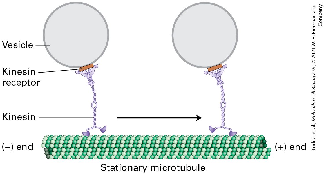
FIGURE 18-18 Structure of kinesin-1. (a) Representation of kinesin-1 showing the two intertwined heavy chains, each with a motor domain in the head region. Each head is attached to the coiled-coil stalk by a flexible linker domain. Two light chains associate with the tail of the heavy chain. See R. D. Vale, 2003, Cell 112:467. (b) X-ray structure of the kinesin heads with the microtubule-binding and nucleotide-binding sites (containing ADP) indicated, including the linkers and the beginning of the stalk region. See M. Thormahlen et al., 1998, J. Struct. Biol. 122:30. [Data from F. Kozielski et al., 1997, Cell 91:985–994, PDB ID 3kin.] Description A schematic of kinesin, labeled (a), shows a y shaped tail, long stalk, and two linker units connecting the two head units. An illustration labeled (b) shows a 3 D ribbon and surface diagram. Linkers, connecting the stalk to the tail are indicated, as are A D P binding sites in each of the head units. Kinesin-1-dependent movement of vesicles can be tracked by in vitro motility assays similar to those used to study myosin-dependent movements (see Figure 17-23). In one type of assay, a vesicle or a bead coated with kinesin-1 was added to a glass slide along with a preparation of stabilized microtubules and observed in a microscope. In the presence of ATP, the beads were seen to move in one direction along a microtubule. Researchers found that beads coated with kinesin-1 always moved from the to the end of a microtubule (Figure 18-19). Thus kinesin-1 is a end–directed microtubule motor protein, and additional evidence shows that it mediates anterograde transport of organelles along the axon.
The Kinesins Form a Large Protein Superfamily with Diverse Functions
FIGURE 18-19 Model of kinesin-1-catalyzed vesicle transport. Kinesin-1 molecules, attached to receptors on the vesicle surface, transport the vesicles from the end to the end of a stationary microtubule. ATP is required for movement. See R. D. Vale et al., 1985, Cell 40:559; and T. Schroer et al., 1988, J. Cell Biol. 107:1785. Description The illustration shows the movement of vesicles along a microtubule by kinesin. The vesicle is represented by a circle attached to the tail of kinesin by a rectangular shaped structure labeled kinesin receptor. One of the heads of the kinesin is attached to the stationary microtubule at the bottom. The microtubule is made up of lines of tubulin units stacked together, which are represented by spheres of two colors arranged alternatively to form a tubular structure. The kinesin moves from the negative end to the positive end of the microtubule. The Kinesins Form a Large Protein Superfamily with Diverse Functions
Following the discovery of kinesin-1, a number of proteins with similar motor domains were identified by both genetic screens and molecular biology approaches. There are now 14 known classes of kinesins in animals, defined as sharing amino acid sequence homology with the motor domain of kinesin-1. Proteins of the kinesin superfamily are encoded by about 45 genes in the human genome. Although the functions of all these proteins have not yet been elucidated, some are involved in organelle, mRNA, and chromosome transport; microtubule sliding; and microtubule depolymerization. As with the different classes of myosin motors, in the kinesin families the conserved motor domain is fused to a variety of class-specific nonmotor domains (Figure 18-20). Whereas kinesin-1 has two identical heavy chains and two identical light chains, members of the kinesin-2 family (also involved in organelle transport) have two different heavy-chain motor domains and a third polypeptide that associates with the tail and binds cargo. Members of the bipolar kinesin-5 family have four heavy chains, forming bipolar motors that can cross-link antiparallel microtubules and, by walking toward the end of each microtubule, slide them past each other. The kinesin-14 motor proteins are the only known class to move toward the end of a microtubule; this class functions in mitosis. Members of the kinesin-13 family have two subunits, but with the conserved kinesin domain in the middle of the polypeptide. Kinesin-13 proteins do not have motor activity; instead, they are special ATPhydrolyzing proteins that can enhance the depolymerization of microtubule ends (see Figure 18-15).
FIGURE 18-20 Structure and function of selected members of the kinesin superfamily. Examples of the structure and mode of action of some kinesin family members. Different kinesins have been given many different names; we use the unified nomenclature described in C. J. Lawrence et al., 2004, J. Cell Biol. 167:19–22. See R. D. Vale, 2003, Cell 112:467. Description The illustration has three parts. The first part shows kinesin -1 (conventional) and Kinesin-2 (heterotrimeric). Kinesin -1 has a Y-shaped structure attached to a long
Kinesin-1 Is a Processive Motor
twisted stalk made of two rope-like structures connected to two oval shaped structures. Kinesin-2 has a similar structure to kinesin-1 except that it has a horizontal C-shaped structure attached to a long stalk made of two rope like structures with two different colors connected to two oval shaped structures of the stalks respective colors. The microtubule is made up of lines of tubulin units stacked together, which are represented by spheres of two colors arranged alternatively to form a tubular structure. The head portion of kinesin -1 (conventional) and Kinesin-2 (heterotrimeric) are attached to the microtubule while their tails are each bound to a round structure labeled organelle transport. These proteins move from the negative end to the positive end of the microtubule. The second part shows the structure of kinesin-5 (bipolar). It has a structure to kinesin-1 except the Y shaped structure is replaced by two oval units same as the oval units below. Two microtubules one above the other are attached to a head unit above and below of kinesin -5. The head units move in opposite directions, which are from the negative end to the positive end of the microtubules to cause sliding of the microtubules. The third part shows the structure of kinesin-13 which has two oval head units attached to a tiny short stalk. They are bound both the positive and negative ends of the microtubule and end disassembly. Kinesin-1 Is a Processive Motor Optical trap and fluorescence-labeling techniques similar to those used to characterize myosin (see Figures 17-28 and 17-29) have been used to study how kinesin-1 moves down a microtubule and how ATP hydrolysis is converted into mechanical work. Such experiments demonstrate that kinesin-1 is a highly processive motor, meaning that it takes hundreds of steps down a microtubule without dissociating from it. During this process, the double-headed molecule moves along the same protofilament within the microtubule. The two heads work in a coordinated manner so that one is always attached to the microtubule.
The kinesin-1 heads bind a microtubule very tightly when they are in either an ATP-bound or nucleotide-free state, but binding is weak when ADP occupies the nucleotide-binding sites. It is these properties that account for the ability of kinesin-1 to move cargo in a processive manner. The ATP cycle of kinesin-1 movement is most easily understood if we begin just after the motor has taken a step (Figure 18-21a). At this point, the motor has a nucleotide-free leading head, which is strongly bound to a tubulin dimer in a protofilament, and an ADP-bound trailing head, which is weakly associated with the protofilament (Figure 18-21a, state 1 ). ATP then binds to the leading head (Figure 18-21a, state 2 ), and this binding induces a conformational change so that the neck linker of this leading head is no longer free and pointing backward, but now swings forward and docks into the head. This swinging motion causes the linker domain to rotate forward, which throws the trailing head — like throwing a ballet dancer — into position to become the leading head (Figure 18-21a, state 3 ). The new leading head finds the next binding site 16 nm ahead on the microtubule (Figure 18-21a, state 4 and Figure 18-21b). This step, which moves the cargo 8 nm, is the power stroke. The interaction of the leading head with the microtubule induces coordinated events between the two heads. First, it induces the leading head to release ADP to generate the nucleotide-free state and therefore bind the microtubule tightly. Second, it induces the trailing head to hydrolyze ATP to ADP and , and upon releasing transition into the weakly bound state (Figure 18-21a, step 5 ). ATP can now bind to the leading head to repeat the cycle and allow the protein to take another step down the microtubule. During this cycle, one head is always in the ATP or nucleotide-free state, both of which result in tight binding to the microtubule, so kinesin very rarely dissociates as it
walks along a microtubule, thereby accounting for its ability to take thousands of steps along a microtubule without disassociating from it.
FIGURE 18-21 Kinesin-1 uses ATP to walk down a microtubule. (a) In this diagram, the two kinesin heads are shown with differently colored linker domains (yellow and red) to distinguish them. The cycle is shown starting after kinesin has taken a step, with the leading head in the nucleotide-free state and tightly bound to the microtubule, while the trailing head is weakly bound to the microtubule because it has ADP bound (state 1 ). The leading head then binds ATP (state 2 ), which induces a conformational change that causes the yellow linker region to swing forward and dock into its associated head domain, thereby thrusting the trailing head forward (state 3 ). The new leading head now finds a binding site 16 nm down the microtubule, to which it binds weakly (state 4 ). The leading head
releases ADP and binds tightly to the microtubule, and coordinately the trailing head hydrolyzes ATP to ADP and , and releases . This converts the trailing head into a weak binding state, and also releases the docked linker region (state 5 ). The cycle now repeats itself for another step. See R. D. Vale and R. A. Milligan, 2000, Science 288:88. (b) Structural model of two kinesin heads (purple) bound to a protofilament in a microtubule. The trailing head, at left, has bound ATP and has thrust the other head into the leading position. Notice how the linker region (yellow) is docked into the trailing head, whereas the linker region (red) of the leading head is still free. [Part (b) Data from E. P. Sablin and R. J. Fletterick, 2004, J. Biol. Chem. 279:15707 and custom PDB files based on 3kin, 1mkj, and 1jff.] Description The illustration labeled (a) shows a five step mechanism. Each step shows a close up of a microtubule as rows of two differently colored spheres alternating each other and kinesin-1 only from the end of the coiled-coil stalk down to the oval shaped heads. Step 1: the left head of the kinesin is bound to a tiny structure called A D P and the right head attached to the microtubule is labeled motor head. The step has a description that reads: The leading head in the nucleotide-free state is strongly bound to the microtubule, whereas the trailing head in the A D P state is weakly bound. Step 2: the left head of the kinesin is bound to a tiny structure and the right head attached to the microtubule has an incision which is labeled neck-linker binding cleft. An A T P molecule is in close vicinity ready to bind to the incision. The step 2 description reads: The leading head binds A T P and remains strongly bound. Step 3: the kinesin-1 moves 16 nanometers ahead by moving the left head in front of the right head. The step 3 description reads: Binding of A T P induces a conformational change causing the linker to swing forward and dock into the head. This motion swings the former trailing head to become the leading head. This is the power stroke as the cargo moves forward. Step 4: shows both heads of the kinesin-1 attached to the microtubule. The step 4 description reads: New leading head finds a binding site on the microtubule 16 nm ahead of its previous site.
Step 5: shows the new trailing head lifting from the microtubule and throwing of a tiny sphere labeled P subscript i. A D P is released from the leading head. The step 5 description reads: Leading head releases A D P and becomes strongly bound. Coordinately, the trailing head hydrolyzes A T P to A D P and P subscript i. With the release of P subscript i, the linker becomes undocked and the head becomes weakly bound to the microtubule. The illustration labeled (b) shows four three-dimensional structures linked together in a line with its positive and negative ends labeled. This structure is also attached to two three-dimensional structures linked together by ribbon structures at the top. As a transporter of organelles, kinesin-1 must bind and transport the correct cargo. It does this through receptor proteins on the appropriate organelle that bind to the tail domain of the motor protein. Since kinesin-1 is an ATPase, it is important that this activity be inactivated to conserve energy when it is not needed and also after releasing the organelle following transport. To accomplish this, kinesin-1 can fold into an inactive state in which the tail domain interacts with the motor head domain to inhibit both its ATPase activity and microtubule binding (Figure 18-22). When the tail binds the cargo-associated receptor protein, the motor unfolds and is activated (step 1 ). When the cargo-activated motor complex encounters a microtubule, it transports the organelle (step 2 ). Upon organelle delivery, kinesin-1 is released from the cargo and is inactivated by refolding into the head-to-tail inhibited state.
FIGURE 18-22 Kinesin-1 is regulated by a head-to-tail interaction. In its inhibited form, the head of kinesin-1 folds back and interacts with the tail. This interaction inhibits the ATPase activity of kinesin-1. When the motor encounters an appropriate receptor, here shown on a vesicle, it unfolds (step 1 ) and is now able to transport the cargo toward the end of a microtubule (step 2 ). It is not yet clear how the motor dissociates from the cargo when they arrive at the destination, but it involves cargo release and folding back into the inhibited state. Description The illustration shows a circular vesicle attached to a tiny rectangular shaped kinesin receptor. The inactive kinesin complex is folded, where there is a head to tail interaction. Kinesin activated by binding cargo occurs. The Y-shaped tail interacts with a vesicle that has a kinesin receptor on the surface, leading to unfolding. The kinesin head groups dock with the tubulins on the stationary microtubule and kinesin actively transports the cargo along the microtubule from the negative end to the positive end.
Dynein Motors Transport Organelles Toward the (−) Ends of Microtubules
When the x-ray crystallographic structure of the kinesin head was determined, it revealed a major surprise — the catalytic core has the same overall structure as myosin’s (Figure 18-23)! This is the case despite the fact that there is no amino acid sequence conservation between the two proteins, arguing strongly that convergent evolution has twice generated a fold that can use the hydrolysis of ATP to generate work. Moreover, the same type of three-dimensional structure is seen in small GTP-binding proteins, such as Ras, that undergo a conformational change upon GTP hydrolysis.
FIGURE 18-23 Convergent structural evolution of the ATP-binding cores of myosin and kinesin heads. The common catalytic cores of myosin and kinesin are shown in yellow, the nucleotide in red, and the lever arm (for myosin-II) and linker domain (for kinesin-1) in light purple. See R. D. Vale and R. A. Milligan, 2000, Science 288:88. [Data from F. Kozielski et al., 1997, Cell 91:985–994, custom PDB file (left) and PDB ID 3kin (right).]
Dynein Motors Transport Organelles Toward the Ends of Microtubules Cells use a different motor protein to transport organelles in a retrograde direction toward the ends of microtubules. Cytoplasmic dynein is very large; the human version is a 1.4-MDa complex consisting of two heavy, two intermediate, two light intermediate, and six light chains. In addition to its role in retrograde transport of organelles toward the ends of microtubules in axons, dynein has many other functions, which we consider later in the chapter. Compared with the myosins and the kinesins, the family of dynein-related proteins is not very diverse. For example, only one gene encodes the human dynein heavy chain. Like kinesin-1, cytoplasmic dynein is a two-headed molecule, built around two heavy chains. A single dynein heavy chain consists of a number of distinct domains (Figure 18-24a). The first is the stem, to which the other dynein subunits bind, and which associates with cargo through another protein complex, dynactin, that we discuss shortly. The next part of the heavy chain is a linker that plays a critical role during ATP-dependent motor activity. A large part of the heavy chain makes up the head containing the AAA ATPase domain, consisting of six repeats that assemble into a flowerlike structure (Figure 18-24b), within which lies the ATPase activity. Embedded between the fourth and fifth AAA repeats is the stalk, which protrudes from the structure and contains the microtubulebinding region.
FIGURE 18-24 The domain structure of cytoplasmic dynein. (a) The dynein heavy chain, consisting of over 4000 amino acid residues, has several distinct domains. Following the stem and linker domains are six AAA repeats (peach, numbered 1–6), with the stalk and its microtubule-binding domain between repeats 4 and 5. (b) The six AAA repeats of each heavy chain assume a structure like petals on a flower. Emerging from this structure is a coiled-coil stalk domain with a microtubule-binding site at the end. A number of additional subunits associate with the stem region and can link dynein to cargo through dynactin (see
Figure 18-26). See R. D. Vale, 2003, Cell 112:467.
Description The illustration labeled (a) shows a chain made of 9 domains. The chain has an N H subscript 2 terminal on the left and a C O O H terminal on the right. The first and second domains are labeled stem and linker, respectively. This is followed by 1, 2, 3, and 4 domains, which is followed by a domain labeled stalk. The stalk is followed by the 5 and 6 domains. The stalk domain is labeled as the microtubule-binding domain. The illustration labeled (b) shows the structure of dynein. It has two heads, each shaped like a circle of flower petals, each petal labeled 1 to 6 respectively. From the 4th petal on each head a tubular projection extends which is labeled stalk. The stalk has a sphere shaped terminal which is labeled microtubule-binding domain. From the first petal on each head a coiled chain labeled linker region extends. Along this chain there are two spheres labeled intermediate chain. Two oval structures bound to each other are bound to the stem. Electron microscopy, combined with x-ray images of the structure of a dynein heavy chain, provides a glimpse of how dynein might work. The first AAA repeat is probably the only one involved in converting the hydrolysis of ATP into mechanical work. In the absence of a bound nucleotide, dynein binds to microtubules. Note that the linker is straight, lies across the AAA domain, and associates with the first and fifth AAA repeats. Upon ATP binding, dynein dissociates from the microtubule and the linker becomes bent. The linker now crosses between the second and third AAA repeats (“pre-stroke”; Figure 18-25a and b, left panels). Interaction with a microtubule, ATP hydrolysis, and release of cause the linker to straighten. This straightening is the power stroke that moves the cargo toward the end of the microtubule (“post-stroke”; Figure 18-25a and b, right panels). The ADP is released, and the motor head remains
bound to the microtubule. When ATP binds, the head is released, and the cycle repeats for another step.
FIGURE 18-25 The power stroke of dynein. (a) Multiple images of purified single-headed dynein molecules in their pre-stroke and post-stroke states were recorded in an electron microscope and then averaged. The image at the left shows dynein in the pre-stroke state, and the image at the right shows it in the post-stroke state. (b) A comparison of the microscopic images combined with structural data shows that the force-generation mechanism involves a change in the position of the linker, which causes a movement of the microtubule-binding stalk. For clarity, only one of the two dynein heads is shown. See G. Bhabha et al., 2014, Cell 159:857. [Part (a) Reprinted by permission from Nature Publishing Group, from S. A. Burgess et al., 2003, “Dynein Structure and Power Stroke,” Nature 421(6924):715–718; permission conveyed through Copyright Clearance Center, Inc.] Description One of the two micrographs labeled (a) is titled pre-stroke. It shows a round structure attached to a tubular structure at the bottom and another tubular structure with an oval shaped ending on the top. The other electron micrograph shows the same structures. The round structure is labeled head, the tubular structure at the bottom is labeled stalk and the tubular structure on the top is labeled stem. A single-headed dynein structure has a heads, shaped like a circle of flower petals, each petal labeled 1 to 6 respectively. From the 4th petal a tubular projection extends which is labeled stalk. The stalk has a sphere shaped terminal. From the first petal a coiled extends to become a stem. The stem has a spherical structure on it. A close up of a microtubule shows rows of two differently colored spheres alternating each other. Their positive and negative ends are labeled. The illustration labeled (b) shows two dynein structures and a microtubule. The first dynein is unattached to the microtubule. The second dynein is attached to the microtubule. There is a shift in the position of the head to the left which is indicated by arrows.
Unlike kinesin-1, cytoplasmic dynein cannot mediate cargo transport by itself. Rather, dynein-related transport requires a large protein complex, called dynactin, that links dynein to its cargo (Figure 18-26). Dynactin consists of 11 different types of subunits, functionally organized into two domains. One domain is built around one actin subunit and eight copies of the actin-related protein Arp1 assembled into a short filament. The end corresponding to the end of this filament is capped by CapZ, the same capping protein that binds the end of an actin filament (see Figure 1712). A number of other subunits are associated with the end. This Arp1-containing domain is responsible for binding cargo. The second domain of dynactin consists of a long protein called , which contains the dynein-binding site and has a microtubule-binding site at one end. Holding the two dynactin domains together is a protein called dynamitin — so named because when it is overexpressed, it dissociates (or “blows apart”) the two domains, making a nonfunctional complex. This feature has been very useful experimentally because it has allowed researchers to identify processes that are dependent on the interaction of dynein and dynactin, which are disrupted in cells overexpressing dynamitin.
FIGURE 18-26 The dynactin complex functions with dynein to transport cargo. (a) One domain of the dynactin complex is built around a short filament made up of eight subunits of the actin-related protein Arp1 and one actin subunit, capped by CapZ. Another domain consists of the protein , which has a microtubule-binding site on its distal end and is also involved in attaching cytoplasmic dynein to the complex. Dynamitin holds the two parts of the dynactin complex together. (b) Diagram of how dynactin and dynein interact with each other and with an activating adaptor and a microtubule. See L. Urnavicius et al., 2015, Science 347:1441. Description The illustration labeled (a) titled dynactin shows a three-dimensional model made up of an A r p 1 filament in the center which is attached to several subunits including actin, cap Z, and dynamitin.
The illustration (b) shows a large rounded structure on the left labeled cargo. Cargo is bound to a rectangular structure which is attached to a coiled-coil labeled activating adaptor. The activating adaptor is attached to dynactin which is made of several subunits represented by various colored rounded structures bound together. One of the subunits labeled dynamitin is attached to another coiled-coil with two rounded structures attached to it in the middle. This coiled-coil has sphere shaped endings and is labeled p 150 superscript glued. It is attached to a microtubule. The activating adapter is also bound to a dynein. Dynein has two flower shaped heads with stalks. One of the stalks is attached to a microtubule. A close up of a microtubule has rows of two differently colored spheres alternating each other. Recent work has shown that the dynein-dynactin complex exists in an inactive form until it encounters activating adaptors, which both activate the motor and link it to cargo. There are many activating adaptors; each functions with a specific cargo. All of the adaptors are dimeric proteins with a distinct cargo-binding site and a long coiled-coil region that interacts with dynactin (Figure 18-26b). In some circumstances, dynein must be transported in an inactive form to a specific location, where it is then activated. For example, it has been found that the dynactin subunit binds TIP protein EB1, allowing dynein to become associated with the growing end of a microtubule. Why would dynein associate with the microtubule end if it is a end–directed motor? Recent work suggests that when dynein is associated with the end of a microtubule via the dynactin-EB1 interaction, it is held in an inactive conformation. When the growing microtubule reaches the cell cortex, the inactive dynein and dynactin encounter an activator that is localized there. The dynein now becomes active, associating with the cortex and pulling on the microtubule that delivered it there! This mechanism has been shown to
help orient the mitotic spindle in yeast, and it probably applies to other situations as well. In addition to dynactin, other proteins function with dynein. One group of proteins, which includes LIS1 and NudE, is involved in regulating the activity of dynein during brain development. NudE links the dynein intermediate and light chains to LIS1 (Figure 18-27a). LIS1 then interacts with the ATPase domain of dynein to lengthen the duration of the power stroke, making the motor more processive under conditions of high load. Defects in LIS1 cause the fatal disease Miller-Dieker lissencephaly (from which the protein got its name); lissencephaly means “smooth brain,” as cortical folds and grooves are lacking in the brains of patients with this condition (Figure 18-27b). Mutations in LIS1 result in defects in both neuronal mitoses and neuronal migration in early development, resulting in the smooth-brain phenotype and defects in mental development as well as many other abnormalities.
Kinesins and Dyneins Cooperate in the Transport of Organelles Throughout the Cell
EXPERIMENTAL FIGURE 18-27 The LIS1 protein, which regulates dynein, is required for brain development. (a) Model of how NudE associates with dynein to allow LIS1 to interact with the ATPase domain of the dynein heavy chain. See R. J. McKenny et al., 2010, Cell 141:304–314. (b) Magnetic resonance images (MRIs) of a normal brain (left) and a brain from a patient with Miller-Dieker lissencephaly (right), which results from a lack of LIS1 function. Notice the absence of folding in the patient’s brain at the locations marked by the arrows. [Part (b) Reprinted with permission from Oxford University Press, from K. Mitsuhiro and W. B. Dobyns, 2003, “Lissencephaly and the Molecular Basis of Neuronal Migration,” Hum. Mol. Genet. 12:R89–R96; permission conveyed through Copyright Clearance Center, Inc.] Description The illustration labeled (a) shows the structure of dynein. Dynein has two flower petal shaped heads with two coiled stalks having sphere shaped ends and two coiled stems with associated structures. Two more coiled-coils labeled N u d E are attached to dynein and are each bound to two spherical structures called L I S 1. This part is highlighted. Two magnetic resonance images labeled (b) shows two brain scans. The one on the left shows a normal brain scan where the brain has many ridges. The one on the right shows a brain scan where the brain has a smoother surface. Kinesins and Dyneins Cooperate in the Transport of Organelles Throughout the Cell Dyneins and kinesins play important roles in the microtubule-dependent organization of organelles in cells (Figure 18-28). Recall that the orientation of microtubules is fixed by the microtubule organizing center,
or MTOC. So the direction of transport — toward or away from the cell center — depends on the motor proteins. For example, the Golgi complex collects in the vicinity of the centrosome, where the ends of microtubules lie, and is driven there by dynein-dynactin. When secretory cargo emerges from the endoplasmic reticulum, it is transported to the Golgi by dynein-dynactin. The endoplasmic reticulum is spread throughout the cytoplasm and is transported there by kinesin-1, which moves toward the ends of microtubules, located toward the cell’s periphery. Some organelles of the endocytic pathway, including late endosomes and lysosomes, are associated with dynein-dynactin complexes. Kinesins transport mitochondria as well as nonmembranous cargo such as mRNAs encoding proteins that need to be localized to specific regions of the cell during development.
FIGURE 18-28 Organelle transport by microtubule motors. Cytoplasmic dyneins (red) mediate retrograde transport of organelles toward the ends of microtubules (cell center); kinesins (purple) mediate anterograde transport toward the ends (cell periphery). Most organelles have one or more microtubule-based motors associated with them. It should be noted that the association of motors with organelles varies by cell type, so some of these associations may not exist in all cells, whereas others not shown here also exist. Description The illustration shows a cell having an oval structure in the center. The oval structure has two cylindrical bodies in it. Seven long thin tubular structures called the microtubules extend in all directions from the oval structure. The far ends of these microtubules have positive ends. Cytoplasmic dynein and kinesin family member are represented by a sphere bound to two tiny spheres below. The color of the bigger spheres in both proteins is different. Beginning at the left, the first microtubule has
nothing on it. Moving counterclockwise, the next microtubule shows a circular structure labeled late endosome, being carried by a cytoplasmic dynein which moves towards the central oval structure. The late endosome becomes a lysosome as it almost reaches the cell center. On the third microtubule, an oval structure labeled is pigment granule is being moved to the left by a kinesin family member and to the right by cytoplasmic dynein. On the fourth microtubule a circular structure labeled early endosome being transported away from the nucleus by a kinesin family member. The fifth microtubule shows an oval shaped mitochondrion being moved to the cell center by cytoplasmic dynein and away by kinesin family member. The sixth microtubule moves through the Golgi apparatus, which has cytoplasmic dynein near it, and moving away from the Golgi is another oval structure labeled secretory vesicle being moved by kinesin family member. The seventh and last microtubule shows a part of endoplasmic reticulum being moved away from the nucleus by kinesin family member. We have seen how kinesin-1 transports organelles in an anterograde direction down axons. What happens to the motor when it gets to the end of the axon? It is carried back in a retrograde direction on organelles transported by cytoplasmic dynein. Thus kinesin-1 and dynein can associate with the same organelle, and a mechanism must exist that turns one motor off while activating the other, although these mechanisms are not yet understood fully. Much of what we know about the regulation of microtubule-based organelle transport comes from studies using fish (e.g., angelfish) or frog melanophores. Melanophores are cells of the vertebrate skin that contain hundreds of dark, melanin-filled pigment granules called melanosomes. Melanophores either have their melanosomes dispersed, in which case they make the skin darker, or aggregated at the cell center, which makes the skin paler (Figure 18-29). These changes in skin color, mediated by
neurotransmitters in the fish and regulated by hormones in the frog, serve to camouflage the fish and enhance social interactions in the frog. The movement of the melanosomes is mediated by changes in intracellular cAMP and is dependent on microtubules. Studies investigating which motors are involved have shown that melanosome dispersion requires kinesin-2, whereas melanosome aggregation requires cytoplasmic dyneindynactin. The first hints of how these activities might be coordinated came from the finding that overexpression of dynamitin inhibited melanosome transport in both directions. This surprising result was explained when it was found that dynactin can bind not only to cytoplasmic dynein but also to kinesin-2 — and may coordinate the activity of the two motors.
FIGURE 18-29 Movement of pigment granules in frog melanophores. (a) Diagram of the microtubule-based reorganization of melanosomes according to the level of cAMP. Melanosomes are aggregated by cytoplasmic dynein and dispersed by kinesin-2. (b) Melanosomes (red) in the dispersed state as seen by immunofluorescence microscopy. Microtubules are labeled green, and the DNA in the nucleus is labeled blue.
Tubulin Modifications Distinguish Different Classes of Microtubules and Their Accessibility to Motors
Description The illustration labeled (a) shows a starfish shaped cell. From the cell center, thin lines extend outwards to reach cell endings. Tiny spherical structures called melanosomes are present all over the cell. the cell is labeled melanosomes dispersed by kinesin-2. Another starfish shaped cell has thin lines extend outwards to reach cell endings. Tiny spherical structures called melanosomes are clumped together at the cell center. This cell is labeled melanosomes aggregated by dynein. A forward arrow labeled low c A M P and a backward arrow labeled high c A M P is present in between these two cells. The immunofluorescence micrograph labeled (b) shows a starfish shaped cell showing the distribution of microtubules and melanosomes. The microtubules are shown fanning out from the centrosome, and the melanosomes are dispersed throughout the cell. A large oval structure is present beside the cell center. The association of dynein and kinesin-2 with the same organelle is not limited to melanosomes. It has been suggested that these motors may cooperate to appropriately localize late endosomes, lysosomes, and mitochondria in some cells. Thus the association of organelles with a number of distinct motors is not the exception but an emerging theme. Tubulin Modifications Distinguish Different Classes of Microtubules and Their Accessibility to Motors The stability and functions of different classes of microtubules are influenced by post-translational modifications to tubulin. Although multiple types of modifications have been detected, we restrict our
discussion here to those that are the best understood — lysine acetylation, detyrosylation, polyglutamylation, and polyglycylation (Figure 18-30a). EXPERIMENTAL FIGURE 18-30 Post-translational modifications of tubulin affect the stability and function of microtubules. (a) Structure of α- and β-tubulin, showing the sites of lysine acetylation on the inner surface of the microtubule and polyglutamylation, polyglycylation, and detyrosylation on the outer surface. Note that polyglutamylation and polyglycylation are likely mutually exclusive, so they would not normally occur at the same time. See J. W. Hamond, D. Cai, and K. J. Verhey, 2008, Curr. Opin. Cell Biol. 20:71–76. (b) Detyrosylated microtubules are preferentially oriented toward the leading edge of a moving cell. A cell migrating toward the right is stained for total microtubules (red) and detyrosylated microtubules (green). The resulting merged image shows the detyrosylated microtubules enriched toward the front of the cell in yellow, which is a combination of red and green. [Part (a) data from E. Nogales, S. G. Wolf, and K. H. Downing, 1998, Nature 391:199–203, PDB ID 1tub.] Description The illustration labeled (a) shows the structure of a microtubule. The microtubule is made up of lines of tubulin units stacked together, which are represented by spheres of two colors arranged alternatively to form a tubular structure. Its negative and positive
ends are labeled. A callout from a dimer in the microtubule shows two ribbon structures enclosed by a surface structure bound together. The first structure is labeled alphatubulin. A part of its ribbon is labeled G l u-G l u-G l u, G l y-G l y-G l y, and T r y. The second structure is labeled beta-tubulin. A part of its ribbon is labeled G l u-G l uG l u and G l y-G l y-G l y. The alpha-tubulin ribbon has a tiny line at the bottom labeled Acetyl-L y s. The fluorescence micrograph labeled (b) shows the concentration of detyrosylated microtubules at the front of a migrating cell as a web of yellow lines surrounded by red and lines. Two of these modifications are found only on α-tubulin. The first is acetylation of the ε-amino group of a specific lysine residue of α-tubulin that lies on the inside of the microtubule. Microtubules with this acetylated lysine are stabilized against breakage and are found on microtubule structures such as centrioles, basal bodies, and primary cilia (primary cilia are discussed in Section 18.5). Indeed, cells unable to acetylate tubulin have defective primary cilia, whereas cells in which the acetylation cannot be removed have unusually stable primary cilia. The second modification of α-tubulin involves its C-terminal tyrosine. This tyrosine can be removed by a carboxypeptidase that functions only when bound to the surface of a microtubule, where it sequentially removes the C-terminal tyrosines from α-tubulin subunits. Such detyrosylated microtubules are more stable, because they are more resistant to depolymerization by kinesin-13 and related proteins. Moreover, in migrating cells, these more stable microtubules are generally oriented toward the front of the cell (Figure 18-30b). When a detyrosylated microtubule depolymerizes, the α-tubulin subunit of the αβ-dimer has the C-terminal tyrosine added back by a tyrosine ligase that acts only on
soluble tubulin, and the αβ-tubulin dimer can now be used during elongation of another growing microtubule. The C-terminal regions of both α- and β-tubulin are rich in glutamic acid residues, and specific enzymes can modify these residues. These modifications occur only after assembly of the microtubule. The tubulin tails can be modified by polyglutamylation, in which a chain of glutamic acid residues is linked to a specific glutamate residue, or by polyglycylation, in which a chain of glycine residues is added to a different glutamate residue. These two modifications are likely mutually exclusive, so that a tubulin subunit modified by polyglycylation is protected from polyglutamylation, and vice versa. Like detyrosylation, both polyglycylation and polyglutamylation can enhance microtubule stability. These post-translational modifications of tubulin not only affect microtubule stability but can also influence the ability of molecular motors to interact with microtubules. Kinesin-1 associates preferentially with detyrosylated and acetylated microtubules, so these modifications may be important in recruiting this motor for axonal transport in neurons. As is illustrated in Figure 18-5e, neurons have different microtubule organizations in their dendrites and their axons. The microtubules in the axon are stabilized by acetylation and detyrosylation, which allows kinesin-1 to associate preferentially with them for axonal transport. Polyglutamylation has a key role in the beating of cilia and flagella, which we discuss in the next section.
Research elucidating the effects of post-translational modifications of tubulin on microtubule function and microtubule-based motors is all quite recent. We can expect future studies to reveal so-called codes used by the cell that distinguish among different classes of microtubules and impart specific functions to the different types of microtubules. KEY CONCEPTS OF SECTION 18.4 Kinesins and Dyneins: Microtubule-Based Motor Proteins Kinesin-1 is a microtubule end–directed ATP-dependent motor protein that transports membrane-bounded organelles (see Figure 18-19). Kinesin-1 consists of two heavy chains, each with an N-terminal motor domain, and two light chains that associate with cargo (see Figure 18-18). The kinesin superfamily includes motors that function in interphase and mitotic cells, transporting organelles and sliding antiparallel microtubules past each other. The superfamily includes one class, kinesin-13, that is not motile but instead destabilizes microtubule ends (see Figure 18-20). Kinesin-1 is a highly processive motor because it coordinates ATP hydrolysis between its two heads so that one head is always firmly bound to a microtubule (see Figure 1821). Kinesin-1 can exist in an inactive folded conformation or in a cargo-associated extended conformation (see Figure 18-22). Cytoplasmic dynein is a microtubule end–directed ATP-dependent motor that associates with the dynactin complex and activating adapters to transport cargo (see Figures 18-24 and 18-26). Kinesins and dyneins associate with many different organelles to organize their locations in cells (see Figure 18-28). Post-translational modifications of tubulin can affect the stability of microtubules and regulate their ability to interact with microtubule-based motors.
Eukaryotic Cilia and Flagella Contain Long Doublet Microtubules Bridged by Dynein Motors
18.5 Cilia and Flagella: Microtubule-Based Surface Structures Cilia and flagella are microtubule-based and membrane-enveloped extensions of the plasma membrane that project from many protozoan and most animal cells. Abundant motile cilia are found on the surfaces of specific epithelia, such as those that line the trachea (see Figure 4-35), where they beat in an orchestrated, wavelike fashion to move fluids. Animal-cell flagella, which are longer than cilia but have a similar structure, can propel a cell, such as a sperm, through liquid. Cilia and flagella contain many different microtubule-based motors: axonemal dyneins are responsible for the beating of flagella and cilia, whereas kinesin-2 and cytoplasmic dynein are responsible for flagellum and cilium assembly and turnover. Eukaryotic Cilia and Flagella Contain Long Doublet Microtubules Bridged by Dynein Motors Cilia and flagella range in length from a few micrometers to more than 2 mm for some insect sperm flagella. They possess a central bundle of microtubules, called the axoneme, which consists of a arrangement
of nine doublet microtubules surrounding a central pair of singlet microtubules (Figure 18-31a, c). Each of the nine outer doublets consists of an A microtubule with 13 protofilaments and a B microtubule with 10 protofilaments (see Figure 18-4). All the microtubules in cilia and flagella have the same polarity: the ends are located at the distal tip. At its point of attachment in the cell, the axoneme connects with the basal body, a complicated structure containing nine triplet microtubules (Figure 1831a, b).
FIGURE 18-31 Structural organization of cilia and flagella. (a) Cilia and flagella are assembled from a basal body, a structure built around nine linked triplet microtubules. Continuous with the A and B microtubules of the basal body are the A and B tubules of the axoneme — the membrane-enveloped core of the cilium or flagellum. Between the basal body and axoneme is the transitional zone. (b) Electron micrograph of a longitudinal section (left) and indicated transverse sections (right) through a basal body and part of the axoneme of a cilium showing the intricate structure of a basal body, the transitional zone,
and axoneme. (c) Diagram of a transverse section of a cilium, to show the identity of the structures. See S. K. Dutcher, 2001, Curr. Opin. Cell Biol. 13:49–54. [Part (b) S. Vaughan, K. Gull, 2015, “Basal Body Structure and Cell Cycle-Dependent Biogenesis in Trypanosoma brucei,” Cilia 5:5, https://doi.org/10.1186/s13630-016-0023- 7.] Description The illustration labeled (a) shows a cilium extended from the cell covered by the plasma membrane. It has a triplet microtubule extending from the basal body. The microtubule is divided into three main parts. Basal body: The first callout shows concentric circle pointing to the basal body from which the microtubule extends. The second callout shows the transverse section of the microtubule in the basal body region. It has a tiny circle in the center. Nine lines from this central circle are each attached to three circles bound to each other. The entire structure looks like a wheel. The third callout is from a region just below the transitional zone. It shows nine groups of three circles bound together in a circle. The three circles are labeled A, B, and C respectively. Transitional zone: The triplet microtubule extends above the basal body to become a doublet microtubule. A callout shows a circle in which there are nine groups of two circles bound together present in a circle enclosing spike like structures. Axoneme: this region is present above the transitional zone. A callout from the top end of the microtubule shows a small circle enclosing two tiny circles bound together. This is enclosed by a bigger circle which also encloses nine groups of two circles bound together present in a circle. A callout from the two circles bound together shows two big circles bound together labeled A and B, as the microtubule now has a doublet form. Several electron micrographs labeled (b) shows a cilium and its sections through a cilium and the arrangement as mentioned above. The following parts are labeled: 9 plus 0 triplet basal body, 9 plus 0 doublet transition zone, basal plate, 9 plus 2 doublet axoneme. The illustration labeled (c) show the transverse section of the nine doublet microtubules. Nine groups of two circular structures called the A and B tubule
Ciliary and Flagellar Beating Are Produced by Controlled Sliding of Outer Doublet Microtubules
respectively are bound together, and are connected by a circular line called nexin inside the plasma membrane. This encloses a central pair of singlet microtubules connected by nexin. Each doublet microtubule is attached to an outer and inner arm dynein represented by tiny hand like projections. The A tubule of all the microtubules are attached to a radial spoke head which extends inwards. The A and B tubule are together called the doublet microtubule. The axoneme is held together by three sets of protein cross-links (Figure 18-31c). The two central singlet microtubules are connected to each other by periodic bridges, like rungs on a ladder. A second set of linkers, composed of the protein nexin, joins adjacent outer doublet microtubules to each other. Radial spokes project from each A tubule of the outer doublets toward the central pair. The major motor protein present in cilia and flagella is axonemal dynein, a large, multisubunit protein related to cytoplasmic dynein. Two rows of axonemal dynein motors are attached periodically down the length of each A tubule of the outer doublet microtubules; these motors are called the inner-arm and outer-arm dyneins (see Figure 18-31c). It is the interaction of these dynein motors with the B tubule in the adjacent doublet that brings about ciliary and flagellar bending. Ciliary and Flagellar Beating Are Produced by Controlled Sliding of Outer Doublet Microtubules
Activation of the axonemal dynein motors causes cilia and flagella to bend. A close examination of this movement using live cell imaging reveals that a bend starts at the base of a cilium or flagellum and then propagates along the structure (Figure 18-32). A clue to how this occurs came from studies of isolated axonemes. In these classic experiments, axonemes were gently treated with a protease that cleaves only the nexin linkers. When ATP was added to the treated axonemes, the doublet microtubules slid past one another as dynein, attached to the A tubule of one doublet, walked down the B tubule of the adjacent doublet (Figure 1833b, c). In an axoneme with intact nexin linkers, the action of dynein induces flagellar bending because the microtubule doublets are connected to one another (Figure 18-33a).
EXPERIMENTAL FIGURE 18-32 Live cell imaging shows flagellar movements that propel sperm and Chlamydomonas forward. In both cases, the cells are moving to the left. (a) In the typical sperm flagellum, successive waves of bending originate at the base and are propagated out toward the tip; these waves push against the surrounding fluid and propel the cell forward. In this sequence, a bend at the base of the flagellum in the first (top) frame has moved distally halfway along the flagellum by the last frame. A pair of gold beads attached to the flagellum are seen to slide apart as the bend moves through their region. (b) Beating of the two flagella on Chlamydomonas occurs in two stages, called the effective stroke (top three frames) and the recovery stroke (remaining frames). The effective stroke pulls the organism through the water. During the recovery stroke, a different wave of bending moves outward from the bases of the flagella, pushing the flagella along the surface of the cell until they reach the position to initiate another effective stroke. Beating commonly occurs 5–10 times per second. [Part (a) C. J. Brokaw, 1991, J. Cell Biol. 114(6):1201–1215; https://doi.org/10.1083/jcb.114.6.1201.] Description Live cell images labeled (a) shows the movement of sperms to the left. The sperm has a oval shaped head with a long thin hair-like tail. There are two dots on the tail. The tail moves in long waves through the pictures. Live cell images labeled (b) shows the motion of the tail of the flagella of Chlamydomonas in 8 frames. Chlamydomonas have circular body with two short tails. They move like frog legs starting at top extended, and by the fourth frame they are up alongside the body, then the move back to extended location.
FIGURE 18-33 Ciliary and flagellar bending is mediated by axonemal dynein. (a) Axonemal dynein attached to an A tubule of an outer doublet pulls on the B tubule of the adjacent doublet trying to move toward the end. Because the adjacent tubules are tethered by nexin, the force generated by dynein bends the cilium or flagellum. (b) Experimental evidence for the model in (a). When the nexin linkers are cleaved with a protease and ATP added to induce dynein activity, the microtubule doublets slide past one another. (c) Electron micrograph of two doublet microtubules in a protease-treated axoneme incubated with ATP. In the absence of cross-linking proteins, doublet microtubules slide excessively. The dynein arms can be seen projecting from A tubules and interacting with B tubules of the left microtubule doublet. Description The illustration labeled (a) shows two doublet microtubules represented by two tubelike structures connected by four tiny tube-like structures labeled as the nexin linkers and five axonemal dyneins represented by a group of tiny oddly shaped structures. The microtubules are connected between the B tubule of one doublet and the A tubule of the other microtubule. This looks like a ladder on its side, with the dynein moving inside the rungs. On activation of dynein, the motor walks towards the negative end of the microtubule, but because the microtubules are constrained by nexin linkers, the microtubule doublets bend. The illustration labeled (a) shows the same illustration as that in (b) except that the nexin linkers are removed by a protease. Now there are no rungs in the sideways ladder. Activation of dynein causes the microtubules to slide past one another. The top side of the ladder is slips to the right. The electron micrograph labeled (c) shows two dark tubular structures, where their ends are on top of each other. The A and B tubules are labeled. Tiny irregular structures on the tubules are labeled axonemal dynein. We don’t yet fully understand how specific subsets of dynein are activated and how a wave of activation is propagated down the axoneme, but posttranslational modifications of tubulin may play a role. Recall from Section
Intraflagellar Transport Moves Material Up and Down Cilia and Flagella
18.4 that post-translational modifications of tubulin subunits can affect the interactions between microtubules and motor proteins. The B tubules of the outer axoneme doublets are often polyglutamylated, and this modification strongly affects the interaction of the inner-arm dynein with the B tubule. Because inner-arm dynein motors mainly affect the waveform of the ciliary beat, it is this aspect of ciliary function that is compromised in mutants unable to undergo polyglutamylation. Intraflagellar Transport Moves Material Up and Down Cilia and Flagella Although axonemal dynein is involved in bending cilia and flagella, another type of motility has been observed in these structures. Careful examination of flagella on the biflagellate green alga Chlamydomonas reinhardtii revealed cytoplasmic particles moving at about toward the tip of a flagellum (anterograde movement) and other particles moving at about from the tip to the base (retrograde movement). This movement, known as intraflagellar transport (IFT), occurs in both cilia and flagella. Light and electron microscopy revealed that the particles move along a path that runs parallel to the outer doublet microtubules and the plasma membrane (Figure 18-34). Analysis of algal mutants demonstrated that the anterograde movement is powered by kinesin-2 and the retrograde movement by cytoplasmic dynein. Remarkably, anterograde-moving particles can move past retrogrademoving particles without interference. This is because the particles move
along distinct microtubules of the outer doublets: the anterogade particles powered by kinesin-2 move along the B-tubule and the retrograde particles powered by dynein move along the A-tubule.
FIGURE 18-34 Intraflagellar transport. (a) Particles are transported between the plasma membrane and the outer doublet microtubules. Transport of the particles to the tip is dependent on kinesin-2, whereas transport toward the base is mediated by cytoplasmic dynein. (b) This thin-section electron micrograph shows IFT particles in a section of a Chlamydomonas flagellum. [Part (b) Reprinted by permission from Nature Publishing Group, from J. L. Rosenbaum and G. B. Witman, 2002, “Intraflagellar Transport,” Nat. Rev. Mol. Cell Biol. 3:813–825; permission conveyed through Copyright Clearance Center, Inc.] Description The illustration labeled (a) shows a section of the flagellum. The flagellum tip is at the top, and the flagellum base is at the bottom. Two tubular structures one on each side is labeled as outer doublet microtubule. They enclose the central tubular structure called
the central microtubule. The plasma membrane is present surrounding these structures. Transport occurs between these and the plasma membrane. Cytoplasmic dynein and kinesin-2 are represented by a sphere bound to two tiny spheres below. The color of the bigger spheres in both proteins is different. On the left side of the illustration on the outer microtubule, three I F T particles represented by spherical structures bound to each other are attached to active kinesin-2 and inactive cytoplasmic dynein proteins. This complex moves upwards towards the positive end of the microtubule. Below, two sets of three I F T particles bound to inactive kinesin-2 and active cytoplasmic dynein moves downwards towards the negative end of the microtubule. A text corresponding to a set of three I F T particles bound to inactive kinesin-2 and active cytoplasmic dynein moving downwards reads: base-directed movement along A-tubule powered by cytoplasmic dynein. On the right side of the right microtubule two sets of three I F T particles bound to inactive kinesin-2 and active cytoplasmic dynein move in opposite directions. A text corresponding to a set of three I F T particles bound to inactive kinesin-2 and active cytoplasmic dynein moving upwards reads: Tip-directed movement along B-tubule powered by kinesin-2. The electron micrograph labeled (b) shows a thin-section of the flagellum also shows particles being moved in the flagellum. Labels along the outer right side of the photo read, from top to bottom, Plasma membrane, Outer doublet microtubule, I F T particles, Outer doublet microtubule, and Plasma membrane. A measurement scale is given for the photo of 100 nanometers. The anterograde and retrograde IFT particles transported in Chlamydomonas flagella have been isolated and their composition determined. They consist of two distinct protein complexes, called IFT complex A and IFT complex B. By analyzing the phenotypes of cells having mutations affecting these complexes, it has been found that complex B is necessary for anterograde IFT, whereas complex A is important for retrograde IFT. Despite this segregation of function, both complexes are transported in both directions. All the components of IFT particles have homologs in organisms containing cilia, such as nematodes,
Primary Cilia Are Sensory Organelles on Interphase Cells
fruit flies, mice, and humans, but these particles are absent from the genomes of yeasts and plants that lack cilia, suggesting that they are specific to IFT. What is the function of IFT? Because all the microtubules in a flagellum have their growing ends at the tip, that is the site where new tubulin subunits and flagellar structural proteins are added. Moreover, even in cells with flagella of uniform length, the microtubules are turning over, with assembly and disassembly occurring at the flagellar tip. In cells defective for kinesin-2, flagella shrink, suggesting that IFT transports new material to the tip for growth. Since IFT is a continually occurring process, what happens to the kinesin-2 molecules when they get to the tip, and where do the dynein motors come from to transport the particles retrogradely? Remarkably and similar to the situation in axonal transport, dynein is carried to the tip as cargo on the anterograde-moving particles, powered by kinesin-2, and then kinesin-2 becomes cargo as the particles are transported back to the base by dynein. Primary Cilia Are Sensory Organelles on Interphase Cells Many vertebrate cells bear a solitary nonmotile cilium known as the primary cilium. The primary cilium is a stable structure that is resistant to drugs such as colchicine that disassemble most microtubules. After colchicine treatment, the only remaining microtubules are found in the centrioles and the primary cilium (see Figure 18-12). Moreover, the
tubulin in the primary cilium is highly acetylated, so using antibodies that specifically recognize acetylated α-tubulin readily identifies the single primary cilium on each interphase cell (Figure 18-35a).
FIGURE 18-35 Many interphase cells contain a nonmotile primary cilium. (a) Fluorescence micrograph of mouse epithelial cells stained with antibodies to acetylated α-tubulin (green), which decorate the primary cilia; to pericentrin (magenta), which decorate the centrosome; and to ZO-1 (red), which label the tight junctions that encircle each cell. (b) The centrosome contains two centrioles in the G1 or G0 stage of the cell cycle, with one of the centrioles functioning as a basal body for the primary cilium. During S phase, the centrosome duplicates in preparation for mitosis. As cells enter mitosis, the primary cilium is disassembled and the duplicated centrosomes form the spindle poles. (c) A diagram depicting a section through a nonmotile primary cilium, showing the lack of the central pair of microtubules and dynein arms typical of motile cilia and flagella. (d) Scanning electron micrographs of epithelial cells of a kidney collecting tubule from a wild-type mouse (left) and a mutant mouse defective in a component of the IFT particles. Arrows point to the primary cilia, which are short stubs in the mutant mouse.
[Part (a) Republished with permission from John Wiley & Sons, from B. D. Engel et al., 2011, “A Cell-Based Screen for Inhibitors of Flagella-Driven Motility in Chlamydomonas Reveals a Novel Modulator of Ciliary Length and Retrograde Actin Flow,” Cytoskeleton 68(3):188–203; permission conveyed through Copyright Clearance Center, Inc. Part (d) G. J. Pazour et al., 2000, J. Cell Biol. 151(3):709–718; https://doi.org/10.1083/jcb.151.3.709.] Description The Fluorescence micrograph labeled (a) shows the outlines of many hexagonal cells, the centrosome, and cilia extending from the centrosome represented by different colors. The illustration labeled (b) shows the primary cilium at different stages in the cell cycle. The early G subscript 1 cell has a round nucleus in the center and two tiny cylindrical structures attached to the plasma membrane. One of the two cylindrical structures is the mother centriole and the other is the daughter centriole from the previous cycle. The G subscript 1 or G subscript 0 cell has a round nucleus in the center and two cylindrical structures attached to the plasma membrane. The mother centriole extends out of the plasma membrane to become the cilium. The S phase cell has four cylindrical structures attached to it. Two of the cylindrical structures are labeled daughter centriole of the current cycle, the other two are the daughter centriole of the previous cycle and the cilium. In the cell undergoing mitosis, the left pole has the mother and daughter centriole (current cycle) while the right pole has two daughter centrioles of both the previous and current cycle. These centrioles are labeled as spindle pores. Microtubules extend from the spindle poles to attach to chromosomes in the center. The cycle starts again. The illustration labeled (c) shows a circular ciliary membrane which encloses nine groups of a set of two rings attached to each other present in a circle lining the ciliary membrane. One of the rings in a set is labeled A-tubule while the other is labeled B- tubule. They are together called outer microtubule doublet. One of the two scanning electron micrographs labeled (d) shows epithelial cells of a wild-type mouse and arrows point to long microtubules. The second one shows cells of a mutant mouse and arrows point to microtubules that are very short, almost like dots.
Terminally differentiated cells and dividing cells not in mitosis contain a primary cilium. In the latter case, the presence of the primary cilium is tied to the duplication cycle of the centrioles (discussed in Section 8.6), with the older, mother centriole functioning as the basal body for the assembly of the primary cilium (Figure 18-35b). Thus the centrosome, consisting of the two centrioles and pericentriolar material (see Figure 186), serves both as the basal body for the primary cilium and as the MTOC for the organization of the cytoplasmic array of microtubules. The primary cilium is nonmotile because it lacks the central pair of microtubules and the dynein arms that are found in other cilia and in flagella (Figure 18-35c), but it does retain the IFT transport system. Work in the past several years has shown that the primary cilium is a sensory organelle, acting as the cell’s antenna by detecting extracellular signals. For example, our sense of smell is due to odorants binding to receptors located in the primary cilia of olfactory sensory neurons in the nose (see
Chapter 23). In another example, the rod and cone cells of the eye have a primary cilium with a greatly expanded tip to accommodate the proteins involved in photoreception. The retinal protein opsin moves through the primary cilium at about 2000 molecules per minute, transported by kinesin-2 as part of the IFT system. Defects in this transport cause retinal degeneration. In vertebrates, the primary cilium is the site of action of the Hedgehog signaling pathway, as described in Chapter 16. The primary cilium has a diffusion barrier at its base so that only the appropriate proteins can enter it: globular proteins of 10 kDa have ready access, but proteins above 40 kDa are excluded. Remarkably, transport
Defects in Primary Cilia Underlie Many Diseases
through this barrier has similarities to transport into the nucleus through nuclear pores, and indeed, these two forms of transport have some components in common. Recall that import though nuclear pores requires a gradient of the Ran GTPase and involves binding of cargo proteins to importins (see Section 13.6). Transport of at least some proteins, such as kinesin-2, across the base and into a primary cilium requires both a gradient of the Ran GTPase and importins. Defects in Primary Cilia Underlie Many Diseases For many years, the existence and function of the primary cilium was ignored. However, this situation has changed dramatically over the last decade as we have come to appreciate that defects in intraflagellar transport result in the loss of primary cilia in mice (Figure 18-35d), and many diseases have now been traced to defects in primary cilia and IFT. One of the first clues came from the discovery that loss of a mammalian homolog of a Chlamydomonas IFT protein results in defects in the primary cilia and causes autosomal dominant polycystic kidney disease (ADPKD). It is hypothesized that the primary cilia on the epithelial cells of the kidney collecting tubule act as mechanochemical sensors to measure the rate of fluid flow by the degree to which they are bent. In another example, patients with Bardet-Biedl syndrome have retinal degeneration, polydactyly (from the Greek for “many fingers”), and
obesity. The syndrome can be caused by mutations in any one of 14 genes and has been traced to defects in the function of primary cilia. Many of these genes encode subunits of the BBsome, an octameric complex that forms a coat with structural elements in common with COPI, COPII, and clathrin (described in Chapter 14) and that traffics membrane proteins to cilia. While defects in many of the BBsome’s components do not affect the structure of the primary cilium itself, they result in a lack of specific membrane receptors that would normally be delivered to primary cilia through the interaction of the BBsome with the IFT apparatus. For example, the polydactyly seen in patients with Bardet-Biedl syndrome is due to a loss of localized Hedgehog signaling (see Chapter 16) in the primary cilium that is necessary for patterning during embryogenesis. KEY CONCEPTS OF SECTION 18.5 Cilia and Flagella: Microtubule-Based Surface Structures Cilia and flagella are microtubule-based cell-surface structures with a characteristic central pair of singlet microtubules and nine sets of outer doublet microtubules (see
Figure 18-31). All cilia and flagella grow from basal bodies, structures with nine sets of outer triplet microtubules that are closely related to centrioles. Axonemal dyneins attached to the A tubule on one doublet microtubule interact with the B tubule of another to bend cilia and flagella. Cilia and flagella have a mechanism, intraflagellar transport (IFT), in which material is transported to the tip by kinesin-2 and from the tip back to the base by cytoplasmic dynein. IFT regulates the function and length of cilia and flagella. Many cells have on their surface a single nonmotile primary cilium, which lacks the normal central pair of microtubules and the dynein arms of motile cilia. The primary cilium functions as a sensory organelle, with receptors for extracellular signals localized to its plasma membrane. Due to its sensory function, many diseases result from defects in receptor localization or in the structure of the primary cilium itself.
18.6 Mitosis
18.6 Mitosis Of all the processes that permit the existence and perpetuation of life, perhaps the most critical is the ability of cells to accurately duplicate and then faithfully segregate their chromosomes at each cell division. During the cell cycle, a highly regulated process discussed in Chapter 19, cells precisely duplicate their chromosomes once during a period known as S phase (for DNA synthesis phase). After duplication, the two copies of each duplicated chromosome are held together by proteins called cohesins. The cells then pass through a period called (for gap 2) before entering mitosis, the process by which the duplicated chromosomes are segregated to the daughter cells. Mitosis has to be precise — loss or gain of a chromosome can be lethal to the cell or cause severe complications for the cell. It is estimated that a yeast cell only mis-segregates 1 of its 16 chromosomes every 100,000 cell divisions, which makes mitosis one of the most accurate processes in biology. To achieve this level of accuracy, the process is highly regulated so that it proceeds in an orderly series of steps that are free of errors. In addition, error detection mechanisms proofread the steps. When errors are detected, the process pauses so they can be corrected. The timing and mechanisms that ensure the fidelity of mitosis are regulated by the cell cycle circuitry that we discuss in detail in Chapter 19. Here we limit our discussion of this circuitry as it applies to microtubules and the mechanics of mitosis.
Centrosomes Duplicate Early in the Cell Cycle in Preparation for Mitosis
In outline, the cell has to first organize the assembly of a machine (the spindle) to segregate the chromosomes, then attach the duplicated chromosomes to the spindle so that during segregation one copy of each chromosome moves toward each daughter cell, and finally the cell divides in two so that each daughter cell inherits a complete set of chromosomes. Centrosomes Duplicate Early in the Cell Cycle in Preparation for Mitosis In preparing to separate the chromosomes during mitosis, cells duplicate their MTOCs — their centrosomes — in a manner that is coordinated with the duplication of their chromosomes in S phase (Figure 18-36). As we discuss in Chapter 19, the cell cycle is largely driven by the association of cell-cycle-specific cyclins with cyclin-dependent kinases (CDKs). Two kinases — phase CDK and Plk4 — promote centrosome duplication. The duplicated centrosomes separate as the cell enters mitosis in a process known as centrosome disjunction and then move to opposite sides of the nucleus to become the two poles that will establish the mitotic spindle. The number of centrosomes in animal cells is carefully controlled to ensure the assembly of an appropriate spindle. In fact, many tumor cells have more than two centrosomes, which contributes to genetic instability resulting from mis-segregation of chromosomes and hence aneuploidy (unequal numbers of chromosomes). The reasons why aneuploidy results in cancer are discussed in Chapter 25.
FIGURE 18-36 Relation of centrosome duplication to the cell cycle. Centrosome duplication, which is initiated by the phase CDKs and Plk4 (step 1 ), results in the pair of centrioles (green) separating and a daughter centriole (blue) budding from each. By the phase, growth of the daughter centrioles is complete, but the two pairs of centrioles remain within a single centrosomal complex. Early in mitosis, driven by the activation of M phase CDKs (step 2 ), the centrosome splits, each half nucleates assembly of microtubules, and the two centriole pairs are moved to opposite sides of the nucleus. The amount of pericentriolar material (green area around the centrioles) and the microtubule nucleation activity of the centrosomes increase greatly in mitosis. In mitosis, each MTOC is called a spindle pole. Description In G 1, a pair of centrioles represented by two cylinders is present. In G 2, the centrioles separate, and in the S phase, new daughter centrioles bud from the mother centrioles. In mitosis, the centrioles migrate to the poles of the cells, followed by cell division, leaving each new cell with a pair of centrioles. A new cell cycle repeats.
There are a number of cases in which spindles form in the absence of centrosomes, including plant-cell mitosis and animal-cell meiosis in females. This observation implies that nucleation of microtubules from centrosomes is not the only way in which a spindle can form. Studies exploiting mitotic extracts from frog eggs — extracts that do not contain centrosomes — show that the addition of beads covered with DNA is sufficient to assemble a relatively normal mitotic spindle (Figure 18-37). In this system, the beads induce the assembly of microtubules, and factors in the extract cooperate to make a spindle. One of the factors necessary for this reaction is cytoplasmic dynein, which is proposed to bind to two microtubules and migrate to their ends, thereby drawing them together.
Mitosis Can Be Divided into Five Stages
EXPERIMENTAL FIGURE 18-37 Mitotic spindles can form in the absence of centrosomes. Centrosome-free extracts can be isolated from frog oocytes arrested in mitosis. When fluorescently labeled tubulin (green) is added to the extracts together with beads covered with DNA (red), mitotic spindles spontaneously form around the beads from randomly nucleated microtubules. See K. Kinoshita et al., 2002, Trends Cell Biol. 12:267– 273; and C. Antonio et al., 2000, Cell 102:425. [Republished with permission from Nature Publishing Group, from R. Heald et al., 1996, “Self-Organization of Microtubules into Bipolar Spindles Around Artificial Chromosomes in Xenopus Egg Extracts,” Nature 382(6590):420–425; permission conveyed through Copyright Clearance Center, Inc.]
Mitosis Can Be Divided into Five Stages Mitosis is a carefully orchestrated process that proceeds through several stages, driven by the cell cycle circuitry, with each stage dependent on completion of the previous one (Figure 18-38). We first review events that occur in each of the stages, and then discuss some of the mechanisms that bring them about.
FIGURE 18-38 The stages of mitosis, followed by cytokinesis, in animal cells. Upper panels show stages in cultured cells stained blue for DNA and green for tubulin. Lower diagrams show the different stages and the events that occur in each. Description Seven micrographs and seven illustrations show cells in interphase, prophase, prometaphase, metaphase, anaphase, telophase and cytokinesis.
The micrograph labeled interphase shows a blue colored oval structure in the center with a web of green lines around it. The illustration corresponding to this micrograph shows a cell with an oval structure inside. Thin microtubules extend from a tiny sphere in the cell. A text below reads: chromosome duplication and cohesion, centrosome duplication. The micrograph labeled prophase shows a blue structure in the middle with a web of thin green lines extending from the poles of the blue structure. The illustration corresponding to this micrograph shows a cell with an oval structure inside. The oval structure has worm shaped structures inside. There are two tiny spheres from which thin microtubules extend to cover the cell. A text below reads: Breakdown of interphase microtubule array and its replacement by mitotic asters, mitotic aster separation, chromosome condensation, and kinetochore assembly. The micrograph labeled prometaphase shows a broken blue structure with large green spots on it from which thin green lines extend outwards. The illustration corresponding to this micrograph shows a cell with two tiny spheres at the opposite end of its poles with microtubules extending in all directions. The microtubules are attached to chromosomes move it to the center of the cell. A text below reads: Nuclear envelope breakdown, chromosomes captured, bi-oriented and brought to the spindle equator. The micrograph labeled metaphase shows a blue colored structure in the center with green lines splay at the poles of the cell. The illustration corresponding to this micrograph shows a cell with two tiny spheres at the opposite end of its poles with microtubules extending in all directions. The microtubules align the chromosomes at the center of the cell. A text below reads: Chromosomes aligned at the metaphase plate. The micrograph labeled anaphase shows a blue center area with green spindles on each side. The illustration corresponding to this micrograph shows a cell with spindles as green lines extending from tiny spheres at the poles and the chromatids as blue structures. A text below reads: A P C slash C activated and cohesins degraded. Anaphase A: Chromosome movement to poles. Anaphase B: Spindle pole separation. The micrograph labeled telophase shows separate groups of blue structures and green lines extending over it. The illustration corresponding to this micrograph shows a cell with a red band around the center of the cell with the two areas separated. The cell is
similar to the anaphase cell. A label below reads: Nuclear envelope reassembly, assembly of contractile ring. The micrograph labeled cytokinesis shows an area of green spindles in two groups at the center and blue structure forming on each side. The illustration corresponding to this micrograph shows the red band almost pinching of the cell. Two circular structures form one on each side covered by microtubules. A text below reads: Re-formation of interphase microtubule array, contractile ring forms cleavage furrow. Prophase is the first stage of mitosis. It is preceded by a number of coordinated and dramatic events that are necessary to assemble the spindle and prepare the cell for chromosome segregation and cell division. Some of these processes directly relate to chromosome segregation, while others facilitate mitosis or prepare the cell for the formation of two daughter cells. We discuss these two categories of processes in turn. To prepare the microtubules for mitosis, the interphase array of microtubules is replaced as the duplicated centrosomes gain more pericentriolar material and become more active in microtubule nucleation. Because the assembly of microtubules radiating from these two MTOCs now resembles stars, they are often called mitotic asters. The dynamics of the growing microtubules increases due to changes in the activities of TIPs at their ends. Bipolar kinesin-5 (see Figure 18-20) walks toward the ends of interdigitating microtubules, which slides them apart until the two asters come to lie on opposite sides of the nucleus (Figure 18-39a). The separated centrosomes will become the poles of the mitotic spindle, the microtubule-based structure that separates chromosomes. The cohesins holding together each pair of duplicated chromosomes, or sister
chromatids as they are called at this stage, degrade except at the centromeric region, where the two sister chromatids remain linked by intact cohesins (Figure 18-39b). Also during prophase, specialized structures called kinetochores, which will become sites of microtubule attachment, assemble at the centromeric region of each sister chromatid.
FIGURE 18-39 Separation of mitotic asters in prophase and parts of a condensed chromosome. (a) In prophase, the asters are separated by the bipolar kinesin-5 interacting with overlapping microtubules of opposite polarities. (b) Parts of a condensed chromosome in mitosis. The duplicated chromosome consists of two sister chromatids (each is a single DNA duplex), held together by cohesins at a constricted region called the centromere. The centromere is the site where the kinetochore, which will make attachments to the kinetochore microtubules, forms. Description The illustration labeled (b) shows a cell in prophase stage. It shows a cell with an oval structure inside. The oval structure has worm shaped structures inside. There are two tiny spheres having two cylindrical structures from which astral microtubules extend to cover the cell in al directions. At the top two microtubules are overlapping and have the label: overlapping polar microtubules with opposite polarities. Between these
microtubules are structures labeled Kinesin-5. The positive ends of the microtubules are labeled. The illustration labeled (c) shows condensed chromosome in mitosis. Two chromatids are vertical with a hole at the center and labeled sister chromatids. At the center, the chromatids are being pulled apart by microtubules connected with kinetochore structures. The center area is labeled centromere. Above the centromere, wrapped around the chromatids, is a structure labeled cohesins. As noted, many cellular processes that are not directly related to chromosome segregation are dramatically altered in preparation for cell division. The internal membrane organization (which is normally dependent on the interphase array of microtubules) disassembles in preparation for the equal segregation of organelles into the two daughter cells. Endocytosis and exocytosis cease, and microfilaments rearrange to give rise to a rounded cell. In the nucleus, the nucleolus breaks down and chromosomes begin to condense. The next stage of mitosis, prometaphase, is signaled by disassembly of the nuclear pores and the nuclear lamina that underlies the nuclear envelope. This leads to breakdown of the nuclear envelope and its retraction into the endoplasmic reticulum. Loss of the nuclear envelope enables microtubules assembled from the spindle poles to search for and capture chromosome pairs by associating with their kinetochores. Each chromatid has a kinetochore, so a sister chromatid pair has two kinetochores (see Figure 18-39b). Microtubules from each spindle pole attach to one of the kinetochores. This attachment process is a critical step, which we discuss in detail shortly. The next stage, metaphase, is
The Mitotic Spindle Contains Three Classes of Microtubules
achieved when all the chromosome pairs align at a point equidistant between the two spindle poles. When the cell detects that all chromosomes are attached to the spindle correctly, the next stage, anaphase, is induced by activation of the anaphase-promoting complex or cyclosome (APC/C) (discussed in
Chapter 19). The activated APC/C ultimately leads to the destruction of the cohesins that were holding the sister chromatids together, so that each chromatid can be pulled to its respective pole by the microtubules attached to its kinetochore. This movement is known as anaphase A. A separate and distinct movement also occurs. The poles move farther apart, which elongates the spindle in a process known as anaphase B. Now that the chromosomes have separated, the cell enters telophase, during which the nuclear envelope and nuclear lamina re-form, the chromosomes decondense, and the spindle disperses. Finally, the cell is pinched into two daughter cells by the contractile ring during cytokinesis. The Mitotic Spindle Contains Three Classes of Microtubules Before we discuss the mechanisms involved in the remarkable process of mitosis, it is important to examine the three classes of microtubules that emanate from the spindle poles. The astral microtubules extend from the spindle poles to the cell cortex (Figure 18-40). By interacting with the cortex, the astral microtubules perform the critical function of orienting the spindle to the axis of cell division. The kinetochore microtubules link
the spindle poles to the kinetochores on sister chromatid pairs. During anaphase A, the kinetochore microtubules transport the newly separated chromosomes to their respective poles. The polar microtubules extend from each spindle pole toward the opposite pole and opposite-oriented polar microtubules interact in an antiparallel manner. As we mentioned, it is kinesin-5 walking along the polar microtubules that pushes the duplicated centrosomes apart during prophase.
Microtubule Dynamics Increase Dramatically in Mitosis
FIGURE 18-40 Mitotic spindles have three distinct classes of microtubules. (a) In this high-voltage electron micrograph, a cell in metaphase was made permeable and microtubules were stained with biotin-tagged anti-tubulin antibodies to increase their visibility. The large cylindrical objects are chromosomes. (b) Schematic diagram corresponding to the metaphase cell in (a). Three sets of microtubules (MTs) make up the mitotic apparatus. All the microtubules have their ends at the poles. Astral microtubules project toward the cortex and are linked to it. Kinetochore microtubules are connected to chromosomes. Polar microtubules project toward the cell center with their distal ends overlapping. The spindle pole with its associated microtubules is also known as a mitotic aster. Description The electron micrograph labeled (a) shows dark chromosomes at the equator attached to thin hair-like microtubules radiating from the spindle poles. Fine threads toward the outer edge are labeled astral microtubules. Thicker threads near the chromatids are labeled kinetochore microtubules and a web of thread below center is labeled polar microtubules. The illustration labeled (b) shows the microtubule assembly in metaphase cell. The centrosome poles represented by a tiny sphere with two cylindrical structures inside are each present at opposite poles of the cell. Astral microtubules radiate from the centromere towards the plasma membrane, kinetochore microtubules radiate towards the cell equator, attaching to chromatids by the kinetochores. A zone in the center of the cell contains interdigitated microtubules from each spindle pole, labeled the zone of interdigitation. Microtubules at the poles are labeled pole microtubules. Cell cortex and pole (centrosome) are labeled. The positive and negative ends of all the microtubules are labeled. Microtubule Dynamics Increase Dramatically in Mitosis
Although we have drawn static images of the stages of mitosis, throughout mitosis microtubules are highly dynamic. As we have seen, as cells enter mitosis the ability of their centrosomes to nucleate the assembly of microtubules increases significantly (see Figure 18-36). In addition, microtubules become much more dynamic, allowing them to capture chromosomes and contribute to assembly of the spindle. How was this determined? In principle, one could label microtubules with a fluorescent tag and watch their individual behaviors, but practically speaking, there are too many microtubules in a mitotic spindle to follow individual ones. To get an average value for the dynamic instability of these microtubules, researchers introduced fluorescently labeled tubulin into cells undergoing mitosis, which became incorporated randomly into the cells’ microtubules. They then bleached the fluorescent label in a small region of the mitotic spindle and measured the rate at which fluorescence came back using the technique known as fluorescence recovery after photobleaching (FRAP) (see Figure 4-22). Since fluorescence recovery is due to the assembly of new microtubules from soluble fluorescent tubulin, the rate of recovery represents the average rate at which microtubules turn over. In a mitotic spindle, microtubule half-life is about 15 seconds, whereas in an interphase cell, it is about 5 minutes. It should be noted that these are bulk measurements and that individual microtubules can be more stable or dynamic, as we will see. What makes microtubules more dynamic as the cell enters mitosis? As we discussed in Section 18.2, dynamic instability is a measure of the relative contributions of growth rates, shrinkage rates, catastrophes, and rescues (see Figure 18-9). Analysis of microtubule dynamics in vivo shows that
the enhanced instability of individual microtubules in mitosis is generated mainly by an increase in catastrophes and a decrease in rescues, with little change in rates of growth (i.e., lengthening) or shrinkage (i.e., shortening). Studies with extracts from frog oocytes have suggested that the main factor enhancing catastrophes in both interphase and mitotic extracts is depolymerization by kinesin-13 proteins. This can be seen in an in vitro assay in which microtubule assembly from pure tubulin is nucleated from purified centrosomes (Figure 18-41a). If kinesin-13 is added to the assay, many fewer microtubules are formed. However, if the protein XMAP215, which enhances assembly at the end, is added with the kinesin-13, many microtubules are formed due to a dramatic reduction in catastrophe frequency. It turns out that the activity of kinesin-13 does not change significantly during the cell cycle, whereas the activity of XMAP215 is inhibited by phosphorylation during mitosis (Figure 18-41b). This results in much more unstable (more dynamic) microtubules as the cell enters mitosis (Figure 18-41c). This increase in dynamics is necessary to enhance the probability of chromosome capture by microtubules as described in the next section.
EXPERIMENTAL FIGURE 18-41 Microtubule dynamics increase in mitosis due to loss of a stabilizing MAP. (a) These three panels reveal the ability of centrosomes to assemble microtubules under various conditions: with pure tubulin (left); with tubulin and the destabilizing protein kinesin-13 (middle); and with tubulin, kinesin-13, and the stabilizing protein XMAP215 (Xenopus MAP of 215 kDa) (right). Further analysis shows that the major effect of XMAP215 is to suppress catastrophes induced by kinesin-13. (b) The increased dynamics of microtubules in mitosis is due to the inactivation of XMAP215 by phosphorylation. (c) Diagram comparing the stabilities of microtubules in interphase and in mitosis. Note that in addition to the decrease in stability in mitosis, the ability of MTOCs to nucleate microtubules increases dramatically in mitosis.
Chromosomes Are Captured and Oriented During Prometaphase
[Part (a) Republished with permission from AAAS, from K. Kinoshita et al., 2001, “Reconstitution of Physiological Microtubule Dynamics Using Purified Components,” Science 294(5545):1340–1343; permission conveyed through Copyright Clearance Center, Inc. Part (b) Data from K. Kinoshita, B. Habermann, and A. A. Hyman, 2002, Trends Cell Biol. 12(6):267–273.] Description One of the three micrographs labeled (a) titled tubulin alone shows a spiky star like structure. The second micrograph titled tubulin plus kinesin-13 shows a tiny spherical structure with a single spike. The third micrograph titled tubulin plus kinesin-13 plus X M A P 215 shows a spiky star like structure. A graph labeled (b) depicts the changes in kinesin 13 and X M A P215 activities through the cell cycle. The graph plots time on the horizontal-axis. No units are given. X M A P 215 activity is represented by the left vertical-axis, and kinesin 13 activity represented by right vertical-axis. Kinesin 13 activity is constant throughout the cell cycle, whereas X M A P 215 activity is higher than that of kinesin 13 during interphase, but drops below that of kinesin 13 during mitosis and rises again at the interphase. The illustration labeled (c) shows structures of microtubules corresponding to the graph in (b). They are labeled microtubule stability. At the left, during interphase, a dot with many spokes is labeled stable. During mitosis, this spoke structure is very small and labeled unstable. Again during interphase, a dot with many spokes is labeled stable. Chromosomes Are Captured and Oriented During Prometaphase Kinetochores, the structures that mediate attachment between chromosomes and microtubules, assemble on each sister chromatid during prophase at a region called the centromere. The centromere is a
constricted region of the condensed chromosome defined by a centromeric DNA sequence. Centromeric DNA can vary enormously in size; in budding yeast it is about 125 bp, whereas in humans it is on the order of 1 Mb (see Chapter 7). Kinetochores contain many protein complexes that facilitate the linkage between centromeric DNA and microtubules. In animal cells, the kinetochore consists of a centromeric DNA layer and inner and outer kinetochore layers, with the ends of kinetochore microtubules terminating in the outer layer (Figure 18-42). Yeast kinetochores are attached by a single microtubule to their spindle pole, human kinetochores are attached by about 30 microtubules, and plant chromosomes are attached by hundreds.
FIGURE 18-42 The structure of a mammalian kinetochore. Diagram and electron micrograph of a mammalian kinetochore. The arrows indicate the ends of microtubules that insert into the kinetochore. [Republished with permission from Springer, from B. F. McEwen et al., 1998, “A New Look at Kinetochore Structure in Vertebrate Somatic Cells Using High-Pressure Freezing and Freeze Substitution,” Chromosoma 107(6–7): 366–375; permission conveyed through Copyright Clearance Center, Inc.]
Description The illustration shows vertical sister chromatids a hole at the center. At the center, the chromatids are being pulled apart by microtubules connected with kinetochore structures. Above the hole, wrapped around the chromatids, is a structure labeled cohesins. Microtubules are represented by three straight lines. Kinetochores have three tiny oval structures connected to each other. A callout from this structure shows an electron micrograph showing the kinetochore l on a large dark circle with bands called microtubules extending from it. How does a kinetochore become attached to microtubules in prometaphase? Microtubules nucleated from the spindle poles are very dynamic, and when they contact a kinetochore, either laterally or at their ends, this contact can lead to chromosomal attachment (Figure 18-43a, steps 1a and 1b ). Microtubules that capture kinetochores are selectively stabilized by a reduction in the rate of catastrophes, which increases the chance that the attachment will persist.
FIGURE 18-43 Chromosome capture and congression in prometaphase. (a) In the first stage of prometaphase, chromosomes become attached either to the end of a microtubule ( 1a ) or to the side of a microtubule ( 1b ). The chromosome is then drawn toward the spindle pole by dynein-dynactin that becomes associated with one of the kinetochores of the chromosome and moves toward the end of the microtubule ( 2 ). Eventually, a microtubule from the opposite pole finds and becomes attached to the free kinetochore, and the chromosome is now said to be bi-oriented ( 3 ). The bi-oriented chromosomes then move to a central point between the spindle poles in a process known as chromosome congression. For ease of presentation, only single kinetochore microtubules are shown here. (b) Congression involves bidirectional oscillations of chromosomes, with one set of kinetochore microtubules shortening on one side of the chromosomes and the other set lengthening on the other. The kinetochore also contains many additional protein complexes not shown here. Description
The illustration labeled (a) shows a cell with two circular centromeres at each end with thin microtubules pulling chromosomes to the centromeres. Different chromosomes are labeled 1 a, 1 b, 2, 3 and 3. The illustration labeled (b) shows a chromosome attached to I shaped structures on both sides called kinesin-4. The middle of the chromosome is attached to three microtubules on both sides via tiny structures. These tiny structures are attached to kinesin-13, kinesin-7, and tethered dynactin and dynein complex on both sides. A text reads: Attachment by kinesin-7; microtubule assembly. The left side of the chromosome undergoes growth whereas the right side undergoes shrinkage. The chromosome moves towards the right negative end of the microtubules. A text reads: Force from dynein and microtubule depolymerization by kinesin-13 and by kinesin-4 on chromosome arms. Other studies have uncovered a mechanism involving Ran, a small GTPase, that enhances the chance that microtubules will encounter kinetochores. Recall that proteins destined for import into the nucleus associate with a nuclear import receptor, called an importin (see Figure 13-36). The complexes move from the cytosol through nuclear pores and into the nucleoplasm. The level of Ran⋅GTP is high in the nucleus, because its activator, the guanine nucleotide exchange factor for Ran (Ran-GEF), is localized there by binding to chromatin. In the nucleus, Ran⋅GTP binds to the importin, which changes the conformation of importin, causing it to release the transported protein. Then the importin-Ran⋅GTP complex leaves the nucleus through a nuclear pore to return to the cytosol. In mitosis, Ran-GEF continues to associate with chromatin, so even after nuclear envelope breakdown there is a gradient of Ran⋅GTP around the chromosomes. This Ran⋅GTP releases a protein called TPX from importin. TPX binds the augmin complex and γ-TuRC and associates with the side
Duplicated Chromosomes Are Aligned by Motors and Microtubule Dynamics
of an existing microtubule to nucleate new microtubules at a shallow angle to the mother microtubule (see Figure 18-7c). This enhances the density of microtubules in the vicinity of chromosomes. Once a kinetochore is attached laterally or terminally to a microtubule, dynein-dynactin associates with the kinetochore to move the duplicated chromosome down the microtubule toward the spindle pole. This movement eventually results in an end-on attachment of the microtubule to one kinetochore (Figure 18-43a, step 2 ). This movement helps orient the sister chromatid so that the unoccupied kinetochore on the opposite side is pointing toward the distal spindle pole. Eventually a microtubule from the distal pole will capture the free kinetochore; at this point the sister chromatid pair is said to be bi-oriented (Figure 18-43a, step 3 ). With the two kinetochores attached to opposite poles, the duplicated chromosome is now under tension, being pulled in opposite directions by the two sets of kinetochore microtubules. Duplicated Chromosomes Are Aligned by Motors and Microtubule Dynamics During prometaphase, the chromosomes come to lie at the midpoint between the two spindle poles, called the metaphase plate, in a process known as chromosome congression. During this process, bi-oriented chromosome pairs often oscillate backward and forward before arriving at the metaphase plate. Chromosome congression involves the coordinated activity of several microtubule-based motors together with regulators of
The Chromosomal Passenger Complex Regulates Microtubule Attachment at Kinetochores
microtubule assembly and disassembly (Figure 18-43b). These regulators are localized at the kinetochores, but how they are maintained there is poorly understood — they are not part of the stable kinetochore complexes. The oscillating behavior of chromosomes involves lengthening of microtubules attached to one kinetochore and shortening of microtubules attached to the other kinetochore, all without losing their attachments. In metazoans, several microtubule-based motors associated with the kinetochore contribute to this process. First, dynein-dynactin provides the strongest force, pulling the chromosome pair toward the more distant pole. This movement requires simultaneous shortening of the microtubule, which is enhanced by kinetochore-localized kinesin-13. The microtubules associated with the opposite kinetochore have to grow as the chromosome moves. Anchored at this kinetochore is the kinesin-related motor kinesin-7 (also known as CENP-E), which holds onto the growing end of the lengthening microtubule. Also contributing to congression is another kinesin, chromokinesin/kinesin-4, which associates with the chromosome arms. Kinesin-4, a end–directed motor, interacts with the polar and kinetochore microtubules to pull the chromosomes toward the center of the spindle and as a result, the chromosome arms point away from the closest spindle pole. When the chromosomes have congressed to the metaphase plate, dynein-dynactin is released from the kinetochores and streams down the kinetochore microtubules to the poles. These different activities and opposing forces work together to bring all the chromosomes to the metaphase plate, at which point the cell is ready for anaphase.
The Chromosomal Passenger Complex Regulates Microtubule Attachment at Kinetochores To have healthy daughter cells, the segregation of chromosomes at mitosis must be very accurate, so it is crucial that all chromosomes are bi-oriented before anaphase begins. During the random kinetochore-to-microtubule attachment process, it is possible for mistakes to be made. For example, both kinetochores of a sister chromatid pair might attach to microtubules from the same spindle pole. If such attachments persisted into anaphase, it would result in one cell missing a chromosome and the other having an extra one, which would either be lethal or very detrimental. Cells have two mechanisms to ensure that all chromosomes are correctly bi-oriented before anaphase begins. The first ensures that each individual chromosome is appropriately bi-oriented, and the second ensures that all of the chromosomes are properly bi-oriented. The first mechanism works to ensure that the kinetochore-microtubule interactions are weak until bi-orientation occurs. When a chromosome is correctly bi-oriented, tension is produced across the chromosome, which leads to the kinetochore-microtubule attachments becoming stabilized. To understand how this works, we need to look a bit more closely at the molecular components that link a kinetochore to a microtubule. As we discussed in Chapter 7, kinetochores assemble on regions of chromosomal DNA marked by a centromere-specific H3 histone variant called CENP-A. This variant marks the site for kinetochore assembly. About half a dozen
distinct stable protein complexes, consisting of more than 40 different proteins, have been shown to associate with this centromeric region in yeast. Essentially all these protein complexes are conserved in humans, which is not surprising given the fundamental importance of kinetochores. One of these, the Ndc80 complex, is long and flexible, and many copies of it link the inner kinetochore with the end of the microtubule in a sleevelike arrangement (Figure 18-44a). The function of Ndc80 and many of the associated factors at the kinetochore are regulated by the chromosomal passenger complex (CPC). This complex associates with the inner kinetochore early in mitosis, and among its components is a protein kinase called Aurora B. Once the CPC associates with the kinetochore, Aurora B can phosphorylate several components in its vicinity, including the Ndc80 complex. This loosens the attachment of Ndc80 to the microtubule. The phosphorylation of these components is not stable, as the phosphatase PP1, which is associated with the outer kinetochore, can dephosphorylate them. Thus when the kinetochores on a pair of sister chromatids are not under tension, Ndc80 is continually phosphorylated by Aurora B and dephosphorylated by PP1. The result is a weakening of the interaction between the kinetochore and microtubule. However, when correct bi-orientation occurs, the microtubules pull in opposite directions on both kinetochores, creating tension across the chromosome. This extends the flexible Ndc80 complex, which increases the spacing between the inner and outer kinetochores (Figure 18-44b, c). As a result of these movements, Ndc80 cannot be phosphorylated by Aurora B, and the dephosphorylated state of Ndc80 renders it more firmly attached to the microtubule. In this way, microtubule attachments to bi-oriented chromosomes are selectively stabilized.
FIGURE 18-44 CPC regulation of microtubule-kinetochore attachment. The Ndc80 complex forms a critical and regulated attachment between the kinetochore and microtubule end. (a) Diagram showing the sleevelike arrangement of the Ndc80 complex linking the inner kinetochore to the end of a microtubule embedded in the outer kinetochore. See S. Santaguida and A. Musacchio, 2009, EMBO J. 28:2511–2531. (b) Diagram of the relationship between the chromosomal passenger complex (CPC), which is associated with the inner kinetochore and contains the kinase Aurora B, and the outer kinetochore, where the phosphatase PP1 binds. Notice that when both kinetochores are under tension, the outer kinetochores move away from the CPC; as a result, Aurora B cannot phosphorylate components in the outer kinetochore, which include the microtubule-binding site of the Ndc80 complex. (c) Cell in metaphase stained for tubulin (red), DNA (blue), Aurora B kinase (green), and the outer kinetochore (magenta). Notice how the outer kinetochore is pulled away from Aurora B (inset). [Part (c) Reprinted by permission from Nature Publishing Group, from S. Ruchaud, M. Carmena, and W. C. Earnshaw, 2007, “Chromosomal Passengers: Conducting Cell Division,” Nat. Rev. Mol. Cell Biol. 2007, 8:798–812; permission conveyed through Copyright Clearance Center, Inc.] Description The illustration labeled (a) shows a microtubule with its negative and positive end labeled. The microtubule is made up of lines of tubulin units stacked together, which
are represented by spheres of two colors arranged alternatively to form a tubular structure. The microtubule is attached to a set of two ring-like structures called the outer kinetochore. It is made of the N d c 80 complex. Five coiled coils from this complex extend to attach to the inner kinetochore. It is made of five oval structures attached to five other longer oval structures attached to the C E N P-A on the centromeric chromatin. One of the two illustrations labeled (b) shows a chromosome titled no tension. The chromosomes are together and a area at the center is shows as six spheres bound together labeled C P C containing aurora B. The centromeric chromatin has kinetochores attached to phosphorous molecules on both sides. Two cohesins are bound at the top and bottom of the chromosomes. The other illustration shows a chromosome titled under tension. The sister chromatids have a hole at the center each side bound to three small spheres. At the center, the chromatids are being pulled apart by microtubules connected with kinetochore structures. Above the hole, wrapped around the chromatids, is a structure labeled cohesins. Microtubules are represented by three straight lines. Kinetochores have three tiny oval structures connected to each other. The fluorescence electron micrograph labeled (c) shows outer kinetochores separated by aurora B in a cell in metaphase stage. The CPC is important for bi-orientation of each individual chromosome, but it does not ensure that all chromosomes are bi-oriented before anaphase begins. The second mechanism to ensure correct chromosome segregation is the spindle assembly checkpoint pathway, a signaling pathway that stops the progression of the cell cycle into anaphase until tension is present at all the kinetochores. Even a single unattached, or inappropriately attached, kinetochore can activate the spindle assembly checkpoint pathway and pause the cell cycle until the error is corrected. An unattached kinetochore drives the assembly of the unstable mitotic checkpoint complex (MCC) as described in detail in Chapter 19. The MCC
Anaphase A Moves Chromosomes to Poles by Microtubule Shortening
is an inhibitor of the APC/C and thereby delays entry into anaphase. When all kinetochores are appropriately attached, the MCC disassembles, the APC/C is activated, and the cell proceeds into anaphase. Anaphase A Moves Chromosomes to Poles by Microtubule Shortening The onset of anaphase A is one of the most dramatic movements that can be observed in the light microscope. When the spindle assembly checkpoint has been passed, APC/C activation induces proteolysis of the remaining cohesins holding the sister chromatids together. Suddenly, the two paired sister chromatids separate from each other and are drawn to their respective poles. The movement is sudden because the kinetochore microtubules are under tension, and as soon as the cohesin attachments between the chromatids are removed, the separated chromatids are free to move. Experiments with isolated metaphase chromosomes have shown that anaphase A movement can be powered by microtubule shortening, using the stored structural strain released after removal of the GTP-bound tubulin subunits at the microtubule tip. This mechanism can be nicely demonstrated in vitro. When metaphase chromosomes are added to purified microtubules, they bind preferentially to the ends of the microtubules. Dilution of the mixture to reduce the concentration of free tubulin dimers results in the movement of the chromosomes toward the ends by microtubule depolymerization at the chromosome-bound
ends. In addition, experiments have shown that in Drosophila, two members of the microtubule-depolymerizing kinesin-13 protein family (see Figure 18-15) also contribute to chromosome movement in anaphase A. One of these kinesin-13 proteins is localized at the kinetochore and enhances disassembly there (Figure 18-45, A1 ), and the other is localized at the spindle pole, enhancing depolymerization there (Figure 18-45, A2 ). Thus, at least in the fly where it has been studied, anaphase A is powered in part by kinesin-13 proteins specifically localized at the kinetochore and spindle pole to shorten the kinetochore microtubules at both their and ends, drawing the chromosomes to the poles. In addition, it is hypothesized that the microtubule-severing protein, katanin, may sever microtubules from the γ-TuRC complex at the spindle pole (see
Figure 18-7). This makes new ends available for depolymerization, which contributes to microtubule shortening.
FIGURE 18-45 Chromosome movement and spindle pole separation in anaphase. Anaphase A movement is powered by microtubule-shortening kinesin-13 proteins at the kinetochore ( A1 ) and at the spindle pole ( A2 ). Note that the chromosome arms still point away from the spindle poles due to associated chromokinesin/kinesin-4 members, so the depolymerization force has to be able to overcome the force pulling the arms toward the center of the spindle. Anaphase B also has two components: sliding of antiparallel polar microtubules powered by a kinesin-5 end–directed motor ( B1 ), and pulling on astral microtubules by dynein-dynactin located at the cell cortex ( B2 ). Arrows indicate the direction of movement generated by the respective forces. Description The illustration shows chromosomes moving towards the spindle poles in a cell with the chromatids pointing toward the center of the cell. Kinesin 13 catalyzes the disassembly of the positive end of the microtubule, causing its shortening. This shortening also occurs to the microtubule end attached to the spindle pole.
The Spindle Is Centered and Oriented by a Dynein/Dynactin-Dependent Pathway
Interdigitated microtubules are shown sliding past each other, aided by kinesin 5. Astral microtubules are anchored to the cell cortex by dynein-dynactin, which exerts a pulling force on the microtubule. Anaphase B Separates Poles by the Combined Action of Kinesins and Dynein Anaphase B causes the spindle to elongate by moving the spindle poles farther apart. A major contributor to this movement are the bipolar kinesin-5 proteins (Figure 18-45, B1 ); kinesin-5 is the same kinesin that is responsible for aster separation in prophase. These motors associate with the overlapping polar microtubules, and since they are end– directed motors, they push the poles apart. While this is happening, the polar microtubules have to grow to accommodate the increased distance between the spindle poles. Another motor — the microtubule end– directed cytoplasmic dynein/dynactin, localized and anchored on the cell cortex — pulls on the astral microtubules, which helps separate the spindle poles (Figure 18-45, B2 ). The Spindle Is Centered and Oriented by a Dynein/Dynactin-Dependent Pathway
As we discuss shortly, the center of the spindle defines the plane where cell division will occur. Thus it is critical during prometaphase and metaphase that the spindle is placed centrally in the cell to ensure that the two daughter cells will be of equal size. This orientation and placement of the spindle is mediated by dynein/dynactin using two distinct mechanisms (Figure 18-46). Dynein is recruited to the cell cortex by a cortical anchor, allowing it to pull on astral microtubules to move the spindle. The regulation of the placement of the cortical anchor, and hence active dynein/dynactin, is what orients the spindle. First, the chromosomes send out a signal that inhibits the association of the cortical anchor in the vicinity of the chromosomes. This inhibitory signal is the Ran⋅GTP gradient that we described earlier in this section. The consequence of the Ran⋅GTP inhibitory signal is that cortical association of dynein/dynactin is restricted to the region of the cell around the spindle poles (Figure 18-46, signal 1 ). Second, associated with each spindle pole is a kinase, called polo-like kinase, that can phosphorylate substrates in its vicinity, including the dynein/dynactin cortical anchor. Phosphorylation of the cortical anchor renders it unable to recruit dynein/dynactin to the cortex (Figure 18-46, signal 2 ). Thus, as a spindle pole gets closer to the cortex, dynein/dynactin dissociates and the spindle moves back toward the center being pulled by dynein/dynactin on the more distal side. This tug of war ultimately moves the spindle into a central position in the cell. This function of dynein/dynactin pulling on astral microtubules is the same mechanism that contributes to elongation of the spindle during anaphase B (see Figure 18-45).
FIGURE 18-46 Dynein-dynactin centers and orients the spindle (a) During prometaphase and metaphase, the spindle is oriented and centered in the cell by two signals that regulate the location of the active cortical anchor for dynein. First, the chromosomes generate a Ran⋅GTP gradient (signal 1 ) that inhibits association of the cortical anchor with the local cell cortex. Second, polo-like kinase at the spindle poles phosphorylates substrates in the local vicinity that inhibits the association of dynein-dynactin with the cortical anchor (signal 2 ). See T. Kiyomitsu and I. M. Cheeseman, 2012, Nat. Cell Biol. 14:311–317. Description The illustration shows a cell with thin thread-like structures for spindles and chromosomes being pulled to the centromeres at each side of the cell. The left side of the cell has a highlighted area labeled inactive cortical anchor. Below at the left is a label pointing to a T shape structure. The label reads: Polo-like kinase at the spindle pole inhibits association of dynein-dynactin with the cortical anchor. At the bottom right is a label point to the top and bottom of the chromosome area. This label reads: R a n-G T P gradient from chromosomes inhibits localization of dynein cortical anchor. At the right side of the cell, a small area is labeled: Active dynein-dynactin pulls on
Cytokinesis Splits the Duplicated Cell in Two
astral microtubules to move spindle to the right. Another area highlighted at the right edge of the cell and is labeled active cortical anchor. Cytokinesis Splits the Duplicated Cell in Two During late anaphase and telophase in animal cells, the cell assembles a microfilament-based contractile ring attached to the plasma membrane that will eventually contract and pinch the cell into two, a process known as cytokinesis (see Figure 18-38). The contractile ring is a thin band of actin filaments of mixed polarity interspersed with myosin-II bipolar filaments (see Figure 17-35). On receiving a signal, the ring contracts, first to generate a cleavage furrow and then to pinch the cell into two. Two aspects of the contractile ring are essential to its function. First, it has to be appropriately placed in the cell. It is known that this placement is determined by a signal provided by the spindle, so that the ring forms equidistant between the two spindle poles. The signal is provided, at least in part, by the chromosomal passenger complex (CPC) that regulates the attachment of microtubules to kinetochores during prometaphase (see
Figure 18-44b). Up to anaphase, the CPC is associated with the inner kinetochores of unseparated chromatids. When anaphase begins, the CPC leaves the kinetochores and associates with the overlapping polar microtubules at the center of the spindle (Figure 18-47a). There the CPC recruits another protein complex, centralspindlin, that includes a end–
directed kinesin motor protein, which concentrates at the middle of the spindle due to its motor activity (Figure 18-47b). As anaphase B continues, centralspindlin recruits a guanine nucleotide exchange factor for RhoA to the adjacent region of the plasma membrane. Recall from
Chapter 17 that Rho proteins are small GTP-binding proteins that are activated by exchange factors to catalyze the exchange of GDP for GTP (see Figure 17-40). Once activated, the RhoA⋅GTP activates both a formin protein to drive the nucleation and assembly of actin filaments and myosin-II that together make up the contractile ring (Figure 18-47b, c). In this way, the position of the spindle directly defines the site of contractile ring formation, and hence cytokinesis.
EXPERIMENTAL FIGURE 18-47 The chromosomal passenger complex (CPC) remains at the spindle midzone during anaphase and telophase to direct the assembly of the contractile ring. (a) Micrographs of a cell in late anaphase (left) and telophase (right), showing microtubules (red), DNA (blue), Aurora B kinase (green), and kinetochores (magenta). Notice how Aurora B, which is part of the CPC, concentrates in the region where the polar microtubules overlap and where the contractile ring will form. Scale bar . (b) At anaphase, the CPC re-localizes to the region of overlapping microtubules and recruits the centralspindlin complex. This complex contains a kinesin motor that helps to concentrate it near microtubule ends. It recruits and activates a Rho guanine nucleotide exchange factor (RhoA GEF) at the adjacent plasma membrane, which activates RhoA to the GTP-bound form. (c) Pathway showing the interactions that results in the formation of Rho⋅GTP. This activates a formin to drive assembly of actin filaments, and also activates myosin II (discussed in Chapter 17). Together, the actin and myosin form the contractile ring that pinches the cell in two.
[Part (a) Reprinted with permission from Nature Publishing Group, from S. Ruchaud, M. Carmena, and W. C. Earnshaw, 2007, “Chromosomal Passengers: Conducting Cell Division,” Nat. Rev. Mol. Cell Biol. 8:798–812; permission conveyed through Copyright Clearance Center, Inc.] Description One of the two fluorescence electron micrographs labeled (a) a cell in late anaphase stage with an inset showing a close up of one area of green threads. It shows a cell with red endings and blue markings with red spots, thin green hair-like fibers connect to the blue markings. The second micrograph shows a cell in telophase stage with a green band where the contractile ring is and red lines moving away from that band to blue structures at both ends. An illustration labeled (b) shows cells of both late anaphase and telophase stage. In the first cell, an oval structure at the top and bottom portion of the cell is labeled R h o A G E F and is bound to four more oval structures below labeled Aurora B recruits centralspindlin. An arrow points to a second cell which has a red band labeled contractile ring in the middle of it. In both the cells centromeres with microtubules are attached to chromosomes. A flowchart labeled (c) reads: Aurora B (arrow) Centralspindlin (arrow) R h o A G E F (arrow) R h o-G T P. Two arrows point from R h o-G T P. The top arrow flow reads: R h o kinase (arrow) Myosin L C-P l (arrow) Myosin-2 activity (arrow) contractile ring. The bottom arrow from points at R h o-G T P reads Formin (arrow) Actin assembly (arrow) contractile ring. The second important aspect of the contractile ring is the timing of its contraction. If it were to contract before all of the chromosomes had moved to their respective poles, disastrous genetic consequences would ensue. As we discuss in Chapter 19, a signaling pathway has been discovered in budding yeast called the spindle position checkpoint, which pauses the cell cycle to ensure that cytokinesis does not occur until the
Plant Cells Reorganize Their Microtubules and Build a New Cell Wall in Mitosis
spindle is appropriately oriented. The mechanism of this coordination in animal cells is still being unraveled. Plant Cells Reorganize Their Microtubules and Build a New Cell Wall in Mitosis Interphase plant cells lack a central MTOC that organizes microtubules into the radiating array typical of animal cells. Instead, numerous MTOCs containing γ-tubulin line the cortex of plant cells and nucleate the assembly of transverse bands of microtubules below the cell wall (Figure 18-48, left). These microtubules, which are of mixed polarity, are released from the cortical MTOCs by the action of katanin, a microtubule-severing protein; loss of katanin gives rise to very long microtubules and misshapen cells. The reason for this is that these cortical microtubules, which are cross-linked by plant-specific MAPs, aid in laying down extracellular cellulose microfibrils, the main component of the rigid cell wall (see Figure 20-43).
FIGURE 18-48 Mitosis in a flowering plant cell. Immunofluorescence micrographs (top) and corresponding diagrams (bottom) showing arrangement of microtubules in interphase and mitotic plant cells. A cortical array of microtubules girdles a cell during interphase. As the cell enters prophase, the microtubules (green), together with actin filaments (red), assemble under the cell cortex into a preprophase band, which marks the future cortical division site. As the cell enters prometaphase and metaphase, a spindle similar to that seen in animal cells forms. However, due to the cell wall, cytokinesis in plant cells is very different from that in animal cells. Microtubules deliver vesicles whose membranes are used to assemble a membrane network called a phragmoplast, whose organization is defined by actin filaments linked to the cortical division site. Eventually, the phragmoplast becomes part of the plasma membranes of the two daughter cells. Enzymes secreted from the vesicles then build a cell wall between the two daughter cells. See G. Jürgens, 2005, Annu. Rev. Plant Biol. 56:281–299. [Micrographs courtesy of Susan Wick.] Description The first immunofluorescence micrograph titled interphase shows a rectangular shaped structure made of fine while lines. The corresponding illustration shows a cross section
of a hexagonal plant cell with half the nucleus at the center surrounded by microtubules. The second immunofluorescence micrograph titled prophase shows two oval structures with a bright white band in the middle and bright white poles. The corresponding illustration shows a cross section of a hexagonal plant cell with the nucleus at the center having worm shaped structures surrounded by preprophase band at the center. The third immunofluorescence micrograph titled metaphase shows a bright white oval structure. The corresponding illustration shows a cross section of a hexagonal plant cell with microtubules holding the chromosomes in a line at the center. A line in the center is labeled cortical division site. The fourth immunofluorescence micrograph titled telophase shows a bright white structure in the center. The corresponding illustration shows a cross section of a hexagonal plant cell with microtubules and two nuclei. A plate like structure is present in the center labeled nascent cell plate. The center of the cell has various filaments labeled Actin filaments guiding cell-plate formation toward the cortical division site. Phragmoplast in the center is labeled. Vesicles on the microtubules are labeled membrane vesicles being delivered by microtubules. Although mitotic events in plant cells are generally similar to those in animal cells, formation of the spindle and cytokinesis has unique features in plants (Figure 18-48). Plant cells bundle their cortical microtubules and actin filaments into a preprophase band and reorganize them into a spindle at prophase without the aid of centrosomes. The site of the preprophase band defines the later cortical division site. At metaphase, the mitotic apparatus appears much the same in plant and animal cells. Because plants have cell walls, the division of the cell into two is quite different from animal cells and requires the assembly of a new wall between the daughter cells. Golgi-derived vesicles, which appear at telophase, are transported along microtubules to form the nascent cell
plate. The cell plate expands and is guided toward the division site by actin filaments to form the phragmoplast, a membrane structure that replaces the animal-cell contractile ring. The membranes of the vesicles forming the phragmoplast become the plasma membranes of the daughter cells. The contents of these vesicles, such as polysaccharide precursors of cellulose and pectin, form the early cell plate, which develops into the new cell wall between the daughter cells. KEY CONCEPTS OF SECTION 18.6 Mitosis Mitosis — the accurate separation of duplicated chromosomes — involves a molecular machine comprising dynamic microtubules and microtubule-associated motors. The mitotic spindle has three classes of microtubules, all emanating from the spindle poles: kinetochore microtubules, which attach to chromosomes; polar microtubules, which extend from each spindle pole and overlap in the middle of the spindle; and astral microtubules, which extend to the cell cortex (see Figure 18-40). In the first stage of mitosis, prophase, the nuclear chromosomes condense and the spindle poles move to either side of the nucleus (see Figure 18-38). At prometaphase, the nuclear envelope breaks down and microtubules emanating from the spindle poles capture sister chromatid pairs at their kinetochores. The two kinetochores (one on each chromatid) become attached to opposite spindle poles (bioriented), which allows the chromosome to congress to the middle of the spindle. The chromosomal passenger complex (CPC) associated with the inner kinetochore keeps microtubule attachments weak by the activity of its kinase component Aurora B, which phosphorylates critical kinetochore proteins. When a chromosome is bioriented, tension is generated, and the Aurora B substrates are pulled away from the kinase (see Figure 18-44). Without phosphorylation of kinetochore proteins by Aurora B, the chromosome-kinetochore attachment becomes stable. At metaphase, chromosomes are aligned on the metaphase plate. The spindle assembly checkpoint pathway monitors unattached kinetochores and delays anaphase until all chromosomes are attached.
At anaphase, duplicated chromosomes are separated and moved toward the spindle poles by shortening of the kinetochore microtubules at both the kinetochore and spindle pole (anaphase A). The spindle poles also move apart, pushed by bipolar kinesin-5 moving toward the ends of the polar microtubules (anaphase B). Spindle separation is also facilitated by cortically located dynein pulling on astral microtubules (see Figure 18-45). The spindle is centered and oriented by two signals — a Ran⋅GTP gradient from the chromosomes and a polo-like kinase gradient from the poles — that negatively regulate the presence or activity of cortical anchors for dynein/dynactin. Active dynein pulls on astral microtubules to center the spindle. The position of the contractile ring is directed by the CPC complex that localizes to the middle of the spindle during anaphase. The CPC recruits factors to generate active Rho⋅GTP at the adjacent plasma membrane to drive the assembly of actin filaments and activate myosin-II. The contractile ring then contracts to pinch the cell in two during cytokinesis (see Figure 18-47). In plants, cell division involves the delivery of membranes by microtubules to assemble the phragmoplast, which becomes the plasma membrane of the two daughter cells (see Figure 18-48).
18.7 Intermediate Filaments
18.7 Intermediate Filaments The third major cytoskeletal system of animals is the intermediate filaments (IFs). This name reflects their diameter of about 10 nm, which is intermediate between the 7–8-nm diameter of microfilaments and the 25 nm myosin thick filaments of skeletal muscle. IFs extend throughout the cytoplasm as well as lining the inner nuclear envelope of interphase animal cells (Figure 18-49). IFs have several unique properties that distinguish them from microfilaments and microtubules. 1. They are biochemically much more heterogeneous — that is, many different, but evolutionarily related, IF subunits exist — and are often expressed in a tissue-dependent manner. 2. They have great tensile strength, as is demonstrated by hair and nails, which consist primarily of the intermediate filaments of dead cells. 3. They do not have an intrinsic polarity like microfilaments and microtubules, and their constituent subunits do not bind a nucleotide. 4. Because they have no intrinsic polarity, it is not surprising that there are no motors that use them as tracks. 5. They are much more stable than microfilaments and microtubules, because the subunit exchange rate is much slower. Indeed, a standard way to purify intermediate filaments is to subject cells to harsh extraction conditions in a detergent so that all membranes, microfilaments, and microtubules are solubilized, leaving a residue that is almost exclusively intermediate filaments.
6. Intermediate filaments are not found in all eukaryotes. Fungi and plants lack intermediate filaments, and insects have only one class, represented by two genes.
Intermediate Filaments Are Assembled from Subunit Dimers
EXPERIMENTAL FIGURE 18-49 Localization of two types of intermediate filaments in an epithelial cell. Immunofluorescence micrograph of an epithelial cell doubly stained with antibodies to keratin (red) and lamin (blue). A meshwork of lamin intermediate filaments can be seen underlying the nuclear membrane, whereas the keratin filaments extend from the nucleus to the plasma membrane. These properties make intermediate filaments unique and important structures of metazoans. Their importance is underscored by the identification of hundreds of clinical disorders, some of which are discussed here, associated with mutations in genes encoding IF proteins. To understand their contributions to cell and tissue structure, we first examine the structure of IF proteins and see how they assemble into filaments. Second, we discuss the dynamics of IFs, and third, we describe the different classes of intermediate filaments and the functions they perform. Intermediate Filaments Are Assembled from Subunit Dimers In the human genome intermediate filaments are encoded by 70 different genes in at least five classes. The defining feature of IF proteins is the presence of a conserved α-helical rod domain of about 310 residues that has the sequence features of a coiled-coil motif (see Figure 3-7a). The primary building block of intermediate filaments is a dimer held together through the rod domains, which associate as a coiled coil (Figure
18-50a). Two dimers then associate in an offset fashion to make tetramers, in which the two dimers have opposite orientations (Figure 18-50b). Tetramers are assembled end to end and interlocked into long protofilaments. Four protofilaments associate into a protofibril, and four protofibrils associate side to side to generate the 10-nm filament. Thus an intermediate filament has 16 protofilaments in it (Figure 18-50c). Flanking the rod domain of each dimer are nonhelical N- and C-terminal domains of different sizes, characteristic of each IF class (Figure 18-50d). Because the tetramer is symmetric, intermediate filaments have no polarity. This description of the filament is based on its structure rather than its mechanism of assembly. It is not clear how intermediate filaments are assembled in vivo. Unlike microfilaments and microtubules, there are no known intermediate filament nucleating, sequestering, capping, or filament-severing proteins.
FIGURE 18-50 Structure and assembly of intermediate filaments. Drawings of IF protein dimers, tetramers, and mature intermediate filaments. (a) IF proteins form parallel dimers through a highly conserved coiled-coil core domain. The globular heads and tails are quite variable in length (as shown in more detail in panel d) and sequence among IF classes. (b)
Intermediate Filaments Are Dynamic
A tetramer is formed by antiparallel, staggered, side-by-side association of two identical dimers. (c) Tetramers associate end to end and laterally into a protofibril. In a mature filament, consisting of four protofibrils, the globular domains form beaded clusters on the surface. (d) Comparison of the organization of dimers of vimentin and lamin A. Notice that the lamin protein has a nuclear localization sequence to target it to the nucleus. See H. Hermann et al., 2007, Nat. Rev. Mol. Cell Biol. 8:562. Description The illustration labeled (a) shows a horizontal coiled-coil structure with two sphere shaped endings on both sides. The left side ends with N-terminus and the right side ends with the C-terminus. It is divided into head, rod, and tail regions from the left to right. The illustration labeled (b) shows two I F proteins with ends opposite each other moving together. Each I F protein as the same structure as described in (a). The illustration labeled (c) shows a long tubular structure called protofilament made of four tube-like structures bound together. An area at the center is labeled tetramer. Below this, another twisted long tubular structure is present made of four tube-like structures bound together. Both these structures are also labeled as protofibrils. The illustration labeled (d) shows the structures of vimentin and lamin A are shown. Vimentin is made of two irregularly coiled thread-like structures with ends shaped like bobby pins. On the left the head is labeled. The tail is labeled at the right. Lamin A has a similar structure except the tail ends are big made of several twists and turns. The tail has a sphere attached to it called I g-like fold. The tail is also bound to a bean shaped structure called the nuclear localization sequence. Both these structures are 5 nanometers in length. Intermediate Filaments Are Dynamic
Although intermediate filaments are much more stable than microtubules and microfilaments, IF protein subunits have been shown to be in dynamic equilibrium with the existing IF cytoskeleton. In one experiment, biotinlabeled keratin was injected into fibroblasts; within 2 hours, the labeled protein had been incorporated into the already existing keratin cytoskeleton (Figure 18-51). The results of this experiment and others demonstrate that IF subunits in a soluble pool are able to add themselves to preexisting filaments and that subunits are able to dissociate from intact filaments.
Cytoplasmic Intermediate Filament Proteins Are Expressed in a Tissue-Specific Manner
EXPERIMENTAL FIGURE 18-51 Keratin intermediate filaments are dynamic, as soluble keratin is incorporated into filaments. Monomeric type I keratin was purified, chemically labeled with biotin, and microinjected into living epithelial cells. The cells were then fixed at different times after injection and stained with an antibody to biotin and with antibodies to keratin. (a) At 20 minutes after injection, the injected biotin-labeled keratin is concentrated in small foci scattered throughout the cytoplasm (left) and has not been integrated into the endogenous keratin cytoskeleton (right). (b) After 4 hours, the biotin- labeled keratin (left) and the keratin filaments (right) display identical patterns, indicating that the microinjected protein has become incorporated into the existing cytoskeleton. [© 1991 R. K. Miller, K. Vistrom, and R. D. Goldman, 1991, J. Cell Biol. 113(4):843–855; https://doi.org/10.1083/jcb.113.4.843.] Description One of the two micrographs labeled (a) titled 20 minutes after injection shows tiny structures labeled biotin-keratin subunit. The second micrograph shows hair-like thin filaments labeled keratin I Fs. Two micrographs labeled (b) titled 4 hours after injection show wavy hair-like thin filaments. Cytoplasmic Intermediate Filament Proteins Are Expressed in a Tissue- Specific Manner Sequence analysis of IF proteins reveals that they fall into five homology classes, including four localized to the cytoplasm. These IF classes show a strong correspondence to the developmental origin of the cell type in which the IF protein is expressed (Table 18-2). We discuss the fifth class
— the nuclear lamins — separately, as they perform functions distinct from the cytoplasmic intermediate filaments.
TABLE 18-2 • The Major Classes of Intermediate Filaments in Mammals Description The illustration of a smooth muscle shows a spindle shaped structure covered by a net like structure. These are labeled dense bodies. The illustration of skeletal muscles show two short tubular structures covered with hair-like projections. They are wrapped by Zdisks. The keratins that make up IF protein classes I and II are found in epithelia; class III IF proteins are generally found in cells of mesodermal origin; and class IV IF proteins compose the neurofilaments found in neurons. The lamins, which make up class V, are found lining the nuclei of
all animal tissues. Here we briefly summarize the four homology classes found in the cytoplasm and discuss their roles in specific tissues. Keratins Keratins provide strength to epithelial cells. The first two IF protein homology classes are the so-called acidic and basic keratins. There are about 50 genes in the human genome encoding keratins, about evenly split between the acidic and basic classes. Dimers form consisting of one basic keratin chain and one acidic keratin chain. These dimers then assemble into a filament as described in the previous section. The keratins are by far the most diverse of the IF protein families. Basic and acidic keratin pairs exhibit different expression patterns both among the various types of epithelia as well as during cell differentiation. The hard keratins make up hair and nails. These keratins are rich in cysteine residues that become oxidized to form disulfide bridges, thereby strengthening the proteins. This property is exploited by hair stylists. If you do not like the shape of your hair, the disulfide bonds in your hair keratin can be reduced, the hair reshaped, and the disulfide bonds reformed by oxidation — the result is so-called “permanent” hair curling or hair straightening. The soft keratins, or cytokeratins, are found in epithelial cells. The epidermal-cell layers that make up the skin provide a good example of the function of these keratins (Figure 18-52). The lowest layer of cells, the basal layer, which is in contact with the basal lamina, proliferates
constantly, giving rise to cells called keratinocytes. After they leave the basal layer, the keratinocytes differentiate and express abundant cytokeratins. The cytokeratins associate with specialized attachment sites between cells, creating sheets of cells that can withstand abrasion. The keratinocytes eventually die, leaving dead cells with their cytokeratin network but devoid of all cell organelles. This dead cell layer provides an essential barrier to water evaporation, without which we could not survive. The life of a skin cell, from birth to its loss from the animal as a skin flake, is about one month.
EXPERIMENTAL FIGURE 18-52 Transgenic mice carrying a mutant keratin gene exhibit blistering similar to that in the human disease epidermolysis bullosa simplex. Histological sections through the skin of a normal mouse and a transgenic mouse carrying a mutant K14 keratin gene are shown. In the normal mouse, the skin consists of a hard outer
epidermal layer that covers and is in contact with the soft inner dermal layer. In the skin from the transgenic mouse, the two layers are separated (arrow) due to weakening of the cells at the base of the epidermis. [Republished with permission from Elsevier, from P. A. Coulombe et al., 1991, “Point Mutations in Human Keratin 14 Genes of Epidermolysis Bullosa Simplex Patients,” Cell 66(6):1301–1311; permission conveyed through Copyright Clearance Center, Inc.] In all epithelia, keratin filaments associate with desmosomes, which link adjacent cells together, and hemidesmosomes, which link cells to the extracellular matrix, thereby giving cells and tissues their strength. These structures are described in more detail in Chapter 20. In addition to simply providing structural support, there is increasing evidence that keratin filaments provide some organization to organelles and participate in signal transduction pathways. For example, in response to tissue injury, rapid cell growth is induced. It has been shown that in epithelial cells, the growth signal requires an interaction between a cellgrowth-signaling molecule and a specific keratin. Desmin The class III IF proteins include vimentin, found in mesenchymal cells; GFAP (glial fibrillary acidic protein), found in glial cells; and desmin, found in muscle cells. Desmin provides strength and organization to muscle cells (see cartoons in Table 18-2).
In smooth muscle, desmin filaments link cytoplasmic dense bodies to the plasma membrane to ensure that cells resist overstretching. In skeletal muscle, a lattice composed of a band of desmin filaments surrounds the sarcomere. The desmin filaments encircle the Z disk and are cross-linked to the plasma membrane. Longitudinal desmin filaments cross to neighboring Z disks within the myofibril, and connections between desmin filaments around Z disks in adjacent myofibrils serve to cross-link myofibrils into bundles within a muscle cell. The lattice is also attached to the sarcomere through interactions with myosin thick filaments. Because the desmin filaments lie outside the sarcomere, they do not actively participate in generating contractile forces. Rather, desmin plays an essential structural role in maintaining muscle integrity. In transgenic mice lacking desmin, for example, this supporting architecture is disrupted and Z disks are misaligned. The locations and morphology of mitochondria in these mice are also abnormal, suggesting that these intermediate filaments may also contribute to the organization of organelles. Neurofilaments Type IV intermediate filaments consist of the three related subunits — NF-L, NF-M, and NF-H (for NF light, medium, and heavy) — that make up the neurofilaments found in the axons of neurons (see Figure 18-2). The three subunits differ mainly in the size of their C-terminal domains, and all form obligate heterodimers. Experiments with transgenic mice reveal that neurofilaments are necessary to establish the correct diameter of
Lamins Line the Inner Nuclear Envelope to Provide Organization and Rigidity to the Nucleus
axons, which determines the rate at which nerve impulses are propagated down them. The structural integrity of the skin is essential in order to withstand abrasion. In humans and mice, the K4 and K14 keratin isoforms form heterodimers that assemble into protofilaments. A mutant K14 with deletions in either the N- or the C-terminal domain can form heterodimers in vitro but does not assemble into protofilaments. The expression of such mutant keratin proteins in cells causes IF networks to break down into aggregates. Transgenic mice that express a mutant K14 protein in the basal stem cells of the epidermis display gross skin abnormalities, primarily blistering of the epidermis, that resemble the human skin disease epidermolysis bullosa simplex. Histological examination of the blistered area reveals a high incidence of dead basal cells. The death of these cells appears to be caused by mechanical trauma from rubbing of the skin during movement of the limbs. Without their normal bundles of keratin filaments, the mutant basal cells become fragile and easily damaged, causing the overlying epidermal layers to delaminate and blister (see
Figure 18-52). Like the role of desmin filaments in supporting muscle tissue, the general role of keratin filaments appears to maintain the structural integrity of epithelial tissues by mechanically reinforcing the connections between cells. Lamins Line the Inner Nuclear Envelope to Provide Organization and
Rigidity to the Nucleus The most widespread IF proteins are the class V proteins, the lamins. Lamins are the progenitors of all IF proteins, from which the cytoplasmic IF proteins arose by gene duplication and mutation. They are the major components of a two-dimensional meshwork called the nuclear lamina that lies between the nuclear envelope and the chromatin of the nucleus (Figure 18-53). In humans, three genes encode lamins: one alternatively spliced gene encodes lamins A and C, and two other genes encode lamins B1 and B2. The B-type lamins appear to be the primordial lamin proteins and are expressed in essentially all cells, whereas lamins A and C are developmentally regulated. B lamins are post-translationally prenylated (see Section 10.2), which helps them associate with the inner nuclear envelope membrane. Lamin proteins contain the coiled-coil regions characteristic of intermediate filaments that are needed for dimerization but also have a nuclear localization sequence that targets them to the nucleus as well as a conserved immunoglobulin-like fold (see Figure 1850d).
FIGURE 18-53 The nuclear lamina is attached to chromatin and through LINC complexes to the cytoskeleton. (a) Diagram of part of a nucleus, showing the association of the lamin-containing nuclear lamina with chromatin and, through the two membranes of the nucleus, with the cytoskeleton. Proteins such as the membrane-associated lamin B receptor and emerin tether the lamin intermediate filaments to the inner nuclear membrane. Lamins are also tethered to the inner nuclear membrane by the prenylation of lamin B (not shown). Diverse linkages, called LINC complexes, attach the lamins through the two nuclear membranes to the cytoskeleton. (b) A LINC (linker of nucleoskeleton and cytoskeleton) complex consists of a SUN domain–containing protein that interacts with lamins and extends across the inner nuclear membrane, and a KASH domain–containing protein that interacts with a SUN domain–containing protein in the perinuclear space and crosses the outer nuclear membrane to interact with components of the cytoskeleton. See C. S. Janota et al., 2017, Cell 169:970. Description The illustration labeled (a) shows a part of the the nucleus surrounded by the outer and inner nuclear membranes. Two nuclear pore complexes are present. Inside the inner nuclear membrane, there is a layer of nuclear lamina which encloses the chromatin. Two proteins embedded in the inner membrane and attached to the nuclear lamina are labeled lamin B receptor and emerin. L I N C complexes are traversing both the inner and outer membranes. The illustration labeled (b) shows the area where L I N C complexes are present. At the top in the cytosol area are an actin filament (red beads) and intermediate filament (blue braid) and a microtubule (green circles). Attached to the microtubule is a molecular motor in pink. All of these are attached through the nuclear membrane to structures, the top half labeled different nesprin proteins and the bottom half labeled different S U N proteins. The two halves are joined in a larger label that reads different L I N C complexes. All three of these examples are shown joined to the nuclear lamina at the bottom. The perinuclear space, inner and outer membrane is labeled. Cells that are subject to mechanical stress have a nuclear lamin meshwork to maintain the integrity of the nucleus. Cells with strong cell walls, such
as plant and fungal cells, do not have such a meshwork. The lamin meshwork therefore provides both strength and support to the inner surface of the nuclear membrane. In fact, cells regulate the level of lamin A to match the stiffness of the tissue they are in. Thus neutrophils, for example, which need to move through thin capillaries and migrate through tight interstitial spaces, have a highly lobulated nucleus as a result of very low levels of lamin A. If they had large, rigid nuclei that were resistant to deformation, they might have trouble squeezing through the small spaces found in the extracellular matrix. To provide rigidity, the lamin meshwork is associated with chromatin on one side and attached to the cytoskeleton on the other. Some proteins embedded in the inner nuclear membrane, such as the lamin-B receptor and emerin, can bind both chromatin-associated proteins and lamins (see
Figure 18-53a). Interestingly, transcriptionally silent regions of the genome are preferentially associated with lamins, and recent evidence suggests that lamins play a role in genome organization and DNA repair. Attachment to the cytoskeleton through both the inner and outer nuclear membranes involves proteins with so-called SUN and KASH domains. The SUN domain proteins are synthesized on the endoplasmic reticulum as transmembrane proteins with their SUN domain in the lumen of the endoplasmic reticulum, and sorting signals in their cytoplasmic domain target them to the outer nuclear membrane, which is continuous with the endoplasmic reticulum. They are then transported as membrane proteins through nuclear pores and, upon reaching the inner nuclear membrane, associate with the nuclear lamina (Figure 18-53b). Nesprins are KASH domain–containing transmembrane proteins of the outer nuclear
Lamins Are Reversibly Disassembled by Phosphorylation During Mitosis
membrane oriented so that the KASH domain can associate with the SUN domain of another protein in the perinuclear space. The nesprins, in turn, associate, either directly or through adapters, with intermediate filaments, actin filaments, and microtubules, thereby linking the nucleus to the cytoskeleton (see Figure 18-53b). These attachments are used to move the nucleus to the correct location in a cell as well as transport it, for example, in the long processes of the vertebrate neuroepithelium. Lamins Are Reversibly Disassembled by Phosphorylation During Mitosis For the nuclear envelope to be broken down as cells go from prophase to prometaphase during mitosis, the nuclear lamina has to be disassembled. As we discuss in Chapter 19, protein kinases called mitotic CDKs drive cells into mitosis, and one of their substrates is the lamins. Phosphorylation of lamins A, B, and C results in disassembly of the intermediate filament lattice into lamin dimers. Due to their C-terminal prenylation, lamin B dimers remain associated with the nuclear membrane. As we saw when we discussed mitosis, depolymerization of the nuclear lamin filaments leads to the disintegration of the nuclear lamina meshwork and contributes to disassembly of the nuclear envelope. During telophase, de-phosphorylation by specific phosphatases promotes lamin reassembly, which is critical to re-formation of a nuclear envelope around the daughter chromosomes. The opposing actions of kinases and phosphatases thus provide a rapid mechanism for controlling the assembly state of lamin intermediate filaments. Other intermediate filaments
undergo similar disassembly and reassembly in other phases of the cell cycle. There are over 600 mutations located throughout the human gene for lamin A that are known to cause diseases, collectively called laminopathies. These diseases include cardiomyopathies, muscular dystrophies, lipodystrophy, and aging-related progeria. Some of these mutations cause Emery-Dreifuss muscular dystrophy (EDMD), most likely because the fragile nuclei cannot stand the stress and strains in the muscle tissue, so these cells are the first to show symptoms. Other forms of EDMD have been traced to mutations in emerin, the lamin-binding membrane protein of the inner nuclear envelope, as well as a nesprin and a SUN protein. Yet other mutations in lamin A cause progeria — accelerated aging, such as Hutchison-Gilford progeria (“prematurely old”). It is still a mystery why different mutations in the same human gene can cause such a wide variety of diseases. KEY CONCEPTS OF SECTION 18.7 Intermediate Filaments Intermediate filaments are the only nonpolar fibrous component of the cytoskeleton and are not associated with motor proteins. Intermediate filaments are built from coiled-coil dimers that associate in an antiparallel fashion into tetramers and then into protofilaments, 16 of which make up the filament (see Figure 18-50). There are five major classes of intermediate filament proteins, with the nuclear lamins (class V) being the most ancient and ubiquitous in animal cells. The other four classes show tissue-specific expression (see Table 18-2). Keratins (IF classes I and II) are found in animal hair and nails, as well as in cytokeratin filaments that associate with desmosomes in epithelial cells to provide the
cells and tissue with strength. The class III filaments include vimentin, GFAP, and desmin, which provide structure and order to muscle Z disks and restrain smooth muscle from overextension. The neurofilaments make up class IV and are important for the structure of axons. The lamins are major components of the nuclear lamina. They contribute to genome organization as well as to the rigidity of the nucleus through linkages to the cytoskeleton involving proteins with SUN and KASH domains (see Figure 18-53). Many diseases are associated with defects in intermediate filaments, especially laminopathies, which include a variety of conditions, and mutations in keratin genes, which can cause severe defects in skin (see Figure 18-52).
Intermediate Filament–Associated Proteins Contribute to Cellular Organization
18.8 Coordination and Cooperation Between Cytoskeletal Elements So far, we have discussed the three cytoskeletal filament classes — microfilaments, microtubules, and intermediate filaments — as though they mostly function independently of one another. But in reality that is not the case. We saw, for example, that the microtubule-based mitotic spindle determines the site of formation of the microfilament-based contractile ring. We close this chapter with some other examples of linkages, both physical and regulatory, between cytoskeletal elements and their integration into other aspects of cellular organization. Intermediate Filament–Associated Proteins Contribute to Cellular Organization There is a group of proteins collectively called intermediate filament– associated proteins (IFAPs) that co-purify with intermediate filaments. Among these IFAPs are members of the plakin family, which are involved in attaching intermediate filaments to other structures. Some plakins link keratin filaments to desmosomes, which are junctions between epithelial cells that provide stability to a tissue, and hemidesmosomes, which are located at regions of the plasma membrane where intermediate filaments
Microfilaments and Microtubules Cooperate to Transport Melanosomes
are linked to the extracellular matrix (these topics are covered in detail in
Chapter 20). Other plakins, found bound along intermediate filaments, have binding sites for microfilaments and microtubules. One of these proteins, called plectin, can be seen by immunoelectron microscopy to provide connections between microtubules and intermediate filaments (Figure 18-54). EXPERIMENTAL FIGURE 18-54 Gold-labeled antibody identifies plectin cross-links between intermediate filaments and microtubules. In this immunoelectron micrograph of a fibroblast cell, microtubules are highlighted in red, intermediate filaments in blue, and the short connecting fibers between them in green. Staining with gold-labeled antibodies to plectin (yellow) reveals that these connecting fibers contain plectin. [© 1996 T. M. Svitkina, A. B. Verkhhovsky, and G. G. Borisy, 1996, J. Cell Biol. 135(4):991–1007; https://doi.org/10.1083/jcb.135.4.991.]
Cdc42 Coordinates Microtubules and Microfilaments During Cell Migration
Microfilaments and Microtubules Cooperate to Transport Melanosomes Studies of mutant mice with light-colored coats have uncovered a pathway in which microtubules and microfilaments cooperate to transport melanosomes. The pigment in mammalian hair is produced in cells called melanocytes, cells that are very similar to the fish and frog melanophores discussed earlier (see Figure 18-29). Melanocytes are found in the hair follicle at the base of the hair shaft and contain pigment-laden granules called melanosomes. Melanosomes are transported to the dendritic extensions of melanocytes for subsequent exocytosis to the surrounding epithelial cells. Transport to the cell periphery is mediated, just as in frog melanophores, by a kinesin family member. At the periphery, the melanosomes are then handed off to myosin V and delivered for exocytosis. If the myosin V system is defective, the melanosomes are not captured and stay in the melanocyte cell body. Thus microtubules are responsible for the long-range transport of melanosomes, whereas microfilament-based myosin V is responsible for their capture and delivery at the cell cortex. This type of division of labor — long-range transport by microtubules and short-range transport by microfilaments — has been found in many other systems, from transport in filamentous fungi to transport along axons. Cdc42 Coordinates Microtubules and Microfilaments During Cell Migration
In Chapter 17, we discussed how the polarity of a migrating cell is regulated by small GTPase Cdc42, which results in the formation of an actin-based leading edge at the front of the cell and contraction at the back (see Figure 17-44 and Figure 18-55, step 1 ). It turns out that Cdc42 activation at the cell front also leads to polarization of the microtubule cytoskeleton. This phenomenon was originally studied in wound-healing assays (see Figure 17-43), in which it was noticed that when the cells at the edge of a scratch are induced to polarize and move to fill in the empty space, the Golgi complex is moved to the front of the nucleus toward the cell front. Golgi localization at the front of the cell indicates that the centrosome moves to lie in front of the nucleus (recall that Golgi localization is dependent on the location of the MTOC; see Figures 18-1c and 18-28). Recent studies have suggested how this happens. Active Cdc42 at the front of the cell binds the polarity factor Par6, which results in the recruitment of the dynein-dynactin complex (Figure 18-55, step 2 ). Cortically localized dynein-dynactin then interacts with microtubules, pulling on them to orient the centrosome and hence the whole radial array of microtubules (Figure 18-55, step 3 ). This reorientation of the microtubule system leads to the reorganization of the secretory pathway to deliver secretory products, especially integrins to bind the extracellular matrix, to the front of the cell for attachment to the substratum for cell migration (Figure 18-55, step 4 ).
FIGURE 18-55 Independent Cdc42 regulation of microfilaments and microtubules to polarize a migrating cell. Active Cdc42⋅GTP at the front of the cell leads to Rac and WASp activation, which results in the assembly of a microfilament-based leading edge (step 1 ) (see Figure 17-44). Independently, Cdc42⋅GTP also leads to the capture of microtubule ends and the activation of dynein (step 2 ). Dynein pulls on microtubules to orient the centrosome (step 3 ) toward the front of the cell. This reorientation reorganizes the secretory pathway for the delivery of adhesion molecules carried in secretory vesicles along microtubules to the front of the cell (step 4 ). See S. Etienne-Manneville et al., 2005, J. Cell Biol. 170:895–901. Description An illustration shows a migratory cell shaped almost like a foot. A layer beneath the cell membrane makes up the microfilaments which enclose more microfilaments, microtubules, and intermediate filaments. It has a sphere shaped nucleus and a centrosome with microtubules extending outwards. The following pathway is described: 1. C d c 42-G T P moves via either W A S p or R a c and W A V E, activates A r p 2 slash 3, leading to actin assembly. 2. C d c 42-G T P activates P a r 6, leading to microtubule end capture and dynein activation. 3. shows the centromere and microtubules, green lines, with no labels. 4. shows the ends of the microtubules. An arrow pointing to the right is labeled direction of polarization.
Advancement of Neural Growth Cones Is Coordinated by Microfilaments and Microtubules
Advancement of Neural Growth Cones Is Coordinated by Microfilaments and Microtubules The nervous system depends on the integration and transmission of signals by neurons. Neurons have specialized structures, called dendrites, that receive signals and a single axon that terminates in one or more synapses on a target cell or cells (see Figure 18-2). It is critical that neurons make the right connections; so how are growing axons guided to their correct destinations? As an axon extends, its terminal growth cone senses signals from the extracellular matrix and from other cells that guide it along the right path. Therefore, how the growth cone receives and interprets cues that direct axon growth is critical to the function of the nervous system. Growth cones are very rich in actin, and they typically have a broad lamellipodium and multiple filopodia. Microtubules are also essential for the guidance of growth cones. Recall that axons have microtubules of uniform polarity along which materials for growth of the axon move by axonal transport (see Figure 18-5e). These microtubules extend into the growth cone and, together with actin, which is necessary for the advancement of the growth cone, are involved in guiding its direction of advancement. Although the mechanisms involved have not been fully elucidated, it has been found that a local growth signal alters local actin dynamics, with the result that microtubules extend into the region of the signal. It has also been found that microtubules in the shaft of the axon have post-translational modifications, such as acetylation, that stabilize
them, whereas the more dynamic microtubules in the growth cone often do not (Figure 18-56). EXPERIMENTAL FIGURE 18-56 Localization of actin (red), microtubules (green), and acetylated microtubules (blue) in a small growth cone. Notice how the stable acetylated microtubules are localized to the shaft of the axon and do not penetrate into the dynamic growth cone. [Republished with permission from Elsevier, from E. W. Dent and F. B. Gertler, 2003, “Cytoskeletal Dynamics and Transport in Growth Cone Motility and Axon Guidance,” Neuron 40(2):209–227; permission conveyed through Copyright Clearance Center, Inc.] Description In the first micrograph a blob of red lines is labeled Filopodium, and the label at the top of the micrograph is F-actin. In the second micrograph the label is M Ts, and a green set of threads has woven a stem like shape. In the third micrograph, the label is a c d-M Ts, and the picture shows a very dim short blue stem like shape at the bottom. In the fourth micrograph, the label is merge, and all of the other three are shown together, so it looks like a greenish blue stem with a bright red stringy flower on top. KEY CONCEPTS OF SECTION 18.8 Coordination and Cooperation Between Cytoskeletal Elements
Intermediate filaments are linked both to specific attachment sites on the plasma membrane (called desmosomes and hemidesmosomes) and to microfilaments and microtubules (see Figure 18-54). In animal cells, microtubules are generally used for the long-range delivery of organelles, whereas microfilaments handle their local delivery. The signaling molecule Cdc42 coordinately regulates microfilaments and microtubules during cell migration. The advancement of growth cones in neurons requires the interplay of microfilaments and microtubules.
Key Terms
End of Chapter Visit Achieve to access study tools and to learn more about the content in this chapter. Perspectives for the Future Analyze the Data Chapter References Additional study tools, including videos, animations, and quizzes Key Terms anaphase aneuploidy aster axonal transport axoneme basal body cell cycle centriole centromere centrosome cilium cytokinesis desmin dynein
Review the Concepts
flagellum intermediate filament keratin kinesin kinetochore lamin metaphase microtubule microtubule-associated protein (MAP) microtubule-organizing center (MTOC) mitosis mitotic spindle motor protein neurofilament pericentriolar material phragmoplast plakin polarity primary cilium prometaphase prophase sister chromatid telophase tubulin Review the Concepts
1. Microtubules are polar filaments; that is, one end is different from the other. What is the basis for this polarity, how is polarity related to microtubule organization within the cell, and how is polarity related to the intracellular movements powered by microtubule-dependent motors? 2. Microtubules both in vitro and in vivo undergo dynamic instability, and this type of assembly is thought to be intrinsic to the microtubule. What is the current model that accounts for dynamic instability? 3. In cells, microtubule assembly depends on other proteins as well as tubulin concentration and temperature. What types of proteins influence microtubule assembly in vivo, and how does each type affect assembly? 4. Microtubules within a cell appear to be arranged in specific arrays. What cellular structure is responsible for determining the arrangement of microtubules within a cell? How many of these structures are found in a typical cell? Describe how such structures serve to nucleate microtubule assembly. 5. Many drugs that inhibit mitosis bind specifically to tubulin, microtubules, or both. What diseases are such drugs used to treat? Functionally speaking, these drugs can be divided into two groups based on their effect on microtubule assembly. What are the two mechanisms by which such drugs alter microtubule structure? 6. Kinesin-1 was the first member of the kinesin superfamily to be identified and therefore is perhaps the best-characterized superfamily member. What fundamental property of kinesin was used to purify it?
7. Certain cellular components appear to move bidirectionally on microtubules. Describe how this is possible given that microtubule orientation is fixed by the MTOC. 8. The movement of kinesin motor proteins involves both the motor domain and the linker domain. Describe the role of each domain in kinesin movement, direction of movement, or both. Could kinesin-1 with one inactive head efficiently move a vesicle along a microtubule? 9. What features of the dynactin complex enable cytoplasmic dynein to transport cargo toward the microtubule end? What effect could inhibition of dynactin interaction with the TIP EB1 have on spindle orientation? 10. Cell swimming depends on appendages containing microtubules. What is the underlying structure of these appendages, and how do these structures generate the force required to produce swimming? 11. What effect would dynein inactivation have on kinesin-2dependent IFT? 12. The mitotic spindle is often described as a microtubule-based cellular machine. The microtubules that constitute the mitotic spindle can be classified into three distinct types. What are the three types of spindle microtubules, and what is the function of each? 13. Mitotic spindle function relies heavily on microtubule motors. For each of the following motor proteins, predict the effect on spindle formation, function, or both of adding a drug that specifically inhibits only that motor: kinesin-5, kinesin-13, and kinesin-4.
14. The poleward movement of kinetochores, and hence chromatids, during anaphase A requires that kinetochores maintain a hold on the shortening microtubules. How does a kinetochore hold onto shortening microtubules? 15. Anaphase B involves the separation of spindle poles. What forces have been proposed to drive this separation? What underlying molecular mechanisms are thought to provide these forces? 16. Cytokinesis, the process of cytoplasmic division, occurs shortly after the separated sister chromatids have neared the opposite spindle poles. How is the plane of cytokinesis determined? What are the respective roles of microtubules and actin filaments in cytokinesis? 17. The best strategy for treating a specific type of human tumor can depend on identifying the type of cell that became cancerous to give rise to the tumor. For some tumors that have colonized a distant location (metastasized), identifying the parental cell type can be difficult. Because the type of IF protein expressed is celltype-specific, using monoclonal antibodies that react with only one type of IF protein can help in this identification. What IF proteins would you produce monoclonal antibodies against to identify (a) a sarcoma of muscle cell origin, (b) an epithelial cell carcinoma, and (c) an astrocytoma (glial cell tumor)? 18. Explain why there are no known motors that use intermediate filaments as tracks. 19. Growth cones are highly mobile regions of developing neurons. What prevents the growth cone from moving or collapsing back into the main cell body, as often occurs with lamellipodia?